| No. | Description | Symbol | This Tank
TK-001 | TNO-2 | TNO-3 | TNO-4 | TNO-5 | TNO-6 | TNO-7 | TNO-8 | TNO-9 | TNO-10 | TNO-11 | TNO-12 | TNO-13 | TNO-14 | TNO-15 | TNO-16 | TNO-17 | TNO-18 | Unit |
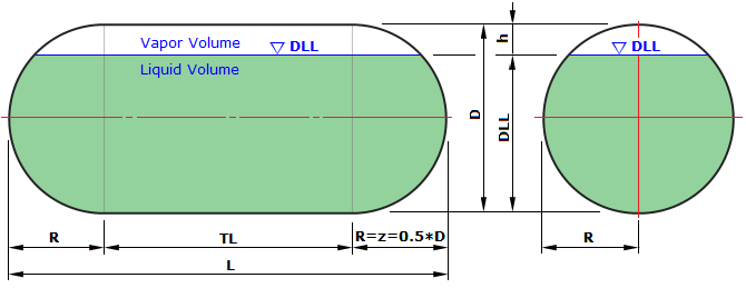
| 1 | TANK In-Diameter | Di = | 10500 | 12000 | 12500 | 12500 | 7500 | 8000 | 8000 | 8250 | 8500 | 9000 | 10000 | 3000 | 11000 | 11250 | 12000 | 12500 | 12000 | 12500 | mm |
| 2 | Hemi-Spherical Depth | z = 0.5*D | 5250 | 6000 | 6250 | 6250 | 3750 | 4000 | 4000 | 4125 | 4250 | 4500 | 5000 | 1500 | 5500 | 5625 | 6000 | 6250 | 6000 | 6250 | mm |
| 3 | Cylinder Straight Length (TL to TL : 10mm 단위올림) | TL = | 17260 | 18530 | 20190 | 22230 | 18770 | 19540 | 24510 | 27240 | 29580 | 22300 | 16260 | 4720 | 24240 | 27720 | 25160 | 22230 | 27370 | 24270 | mm |
| 4 | Total Length ( Head End to End ), L = 2*z +TL | L = | 27760 | 30530 | 32690 | 34730 | 26270 | 27540 | 32510 | 35490 | 38080 | 31300 | 26260 | 7720 | 35240 | 38970 | 37160 | 34730 | 39370 | 36770 | mm |
| 5 | Design Liquid Level | DLL = | 9333 | 10661 | 11109 | 11118 | 6687 | 7132 | 7141 | 7368 | 7593 | 8024 | 8888 | 2665 | 9799 | 10030 | 10686 | 11118 | 10693 | 11125 | mm |
| 6 | | | | | | | | | | | | | | | | | | | | | |
| 7 | Gross Volume, Vnom = Vcyl+Vhead | Vnom = | 2100 | 3000 | 3500 | 3750 | 1050 | 1250 | 1500 | 1750 | 2000 | 1800 | 1800 | 47.5 | 3000 | 3500 | 3750 | 3750 | 4000 | 4000 | m³ |
| 8 | Net Volume ( Vnet = 0.98*Vnom) | Vnet = | 1988.5 | 2840.7 | 3314.2 | 3550.9 | 994.2 | 1183.6 | 1420.4 | 1657.1 | 1893.8 | 1704.4 | 1704.4 | 45.0 | 2840.7 | 3314.2 | 3550.9 | 3550.9 | 3787.6 | 3787.6 | 0.98*Vnom |
| 9 | Vhead = πD³ / 6 | Vhead = | 606.1 | 904.8 | 1022.7 | 1022.7 | 220.9 | 268.1 | 268.1 | 294.0 | 321.6 | 381.7 | 523.6 | 14.1 | 696.9 | 745.5 | 904.8 | 1022.7 | 904.8 | 1022.7 | m³ |
| 10 | Vcyl = πD² / 4 * L | Vcyl = | 1493.9 | 2095.2 | 2477.3 | 2727.3 | 829.1 | 981.9 | 1231.9 | 1456.0 | 1678.4 | 1418.3 | 1276.4 | 33.4 | 2303.1 | 2754.5 | 2845.2 | 2727.3 | 3095.2 | 2977.3 | m³ |
| 11 | Storage Ratio = Vnet / Vnom * 100 | Sratio = | 94.69 | 94.69 | 94.69 | 94.69 | 94.69 | 94.69 | 94.69 | 94.69 | 94.69 | 94.69 | 94.69 | 94.69 | 94.69 | 94.69 | 94.69 | 94.69 | 94.69 | 94.69 | % |
| 12 | Static Head Pressure, Ps = ρgh(h=DLL) | Ps = | 0.0458 | 0.0523 | 0.0545 | 0.0545 | 0.0328 | 0.035 | 0.035 | 0.0361 | 0.0372 | 0.0393 | 0.0436 | 0.0131 | 0.048 | 0.0492 | 0.0524 | 0.0545 | 0.0524 | 0.0545 | MPa |
| 13 | [ASME] Total Design Pressure, P = Po+Ps | P_ASME = | 0.9968 | 1.0033 | 1.0055 | 1.0055 | 0.9838 | 0.986 | 0.986 | 0.9871 | 0.9882 | 0.9903 | 0.9946 | 0.9641 | 0.999 | 1.0002 | 1.0034 | 1.0055 | 1.0034 | 1.0055 | MPa |
| 14 | [ASME] Cylinder Shell Thickness | t_Cyl = | 39.45 | 45.23 | 47.18 | 47.18 | 28.11 | 29.98 | 29.98 | 30.92 | 31.86 | 33.75 | 37.54 | 11.63 | 41.37 | 42.34 | 45.24 | 47.18 | 45.24 | 47.18 | mm |
| 15 | [ASME] Hemi-Spherical Head Thickness | t_HHead = | 20.16 | 23.04 | 24.01 | 24.01 | 14.51 | 15.44 | 15.44 | 15.91 | 16.38 | 17.32 | 19.21 | 6.29 | 21.12 | 21.6 | 23.04 | 24.01 | 23.04 | 24.01 | mm |
| 16 | [ASME] Cylinder Shell Thk (Vacuum Ring Pitch: 3.5m ) | t_CylPe = | 17.0 | 18.0 | 18.5 | 18.5 | 14.5 | 15.0 | 15.0 | 15.0 | 15.5 | 15.5 | 16.5 | 9.0 | 17.5 | 17.5 | 18.0 | 18.5 | 18.0 | 18.5 | mm |
| 17 | [ASME] Allowable External Pressure(Shell), Pe < Pa_Cyl | Pa_Cyl = | 0.0495 | 0.0479 | 0.0485 | 0.0485 | 0.0518 | 0.0515 | 0.0515 | 0.0489 | 0.0512 | 0.0475 | 0.0489 | 0.0544 | 0.0502 | 0.0487 | 0.0479 | 0.0485 | 0.0479 | 0.0485 | MPa |
| 18 | [ASME] Allowable External Pressure(Head ), Pe < Pa_Head | Pa_Head = | 0.1599 | 0.162 | 0.1627 | 0.1627 | 0.1557 | 0.1564 | 0.1564 | 0.1568 | 0.1571 | 0.1578 | 0.1592 | 0.1494 | 0.1606 | 0.161 | 0.162 | 0.1627 | 0.162 | 0.1627 | MPa |
| 19 | [Class] Dynamic Pressure(Ship Motion) | Pgd(max) = | 0.1258 | 0.1323 | 0.1345 | 0.1345 | 0.1328 | 0.135 | 0.135 | 0.1361 | 0.1372 | 0.1393 | 0.1236 | 0.1331 | 0.128 | 0.1292 | 0.1324 | 0.1345 | 0.1324 | 0.1345 | MPa |
| 20 | [Class] Total Design Pressure, P = Po+Pgd(max) | P_Class = | 0.951 | 0.951 | 0.951 | 0.951 | 0.951 | 0.951 | 0.951 | 0.951 | 0.951 | 0.951 | 0.951 | 0.951 | 0.951 | 0.951 | 0.951 | 0.951 | 0.951 | 0.951 | MPa |
| 21 | [Class] Cylinder Shell Thickness | t_Cyl = | 37.69 | 42.93 | 44.68 | 44.68 | 27.21 | 28.95 | 28.95 | 29.83 | 30.7 | 32.45 | 35.94 | 11.48 | 39.43 | 40.31 | 42.93 | 44.68 | 42.93 | 44.68 | mm |
| 22 | [Class] Hemi-Spherical Head Thickness | t_HHead = | 19.28 | 21.89 | 22.76 | 22.76 | 14.06 | 14.93 | 14.93 | 15.36 | 15.8 | 16.67 | 18.41 | 6.22 | 20.15 | 20.59 | 21.89 | 22.76 | 21.89 | 22.76 | mm |
| 23 | [LR] Cylinder Shell Thk (Vacuum Ring: 3.5m ) | t_CylPe = | 18.0 | 19.5 | 19.5 | 19.5 | 15.0 | 15.5 | 15.5 | 15.5 | 16.0 | 16.5 | 17.5 | 9.0 | 18.5 | 18.5 | 19.5 | 19.5 | 19.5 | 19.5 | mm |
| 24 | [DNV-GL] Hemi-Spherical Head Thk (For Vacuum )
Pc=2.4*Et*(t-c/Ro)²/ 3.7 [DNV-GL Pt4-Ch7] | t_HeadPe = | 6.93 | 7.78 | 8.06 | 8.06 | 5.24 | 5.52 | 5.52 | 5.66 | 5.8 | 6.09 | 6.65 | 2.7 | 7.22 | 7.36 | 7.78 | 8.06 | 7.78 | 8.06 | mm |
| 25 | [LR] Allowable External Pressure (Shell DNV-GL, LR, GV) | Pcr = | 0.0498 | 0.0503 | 0.0477 | 0.0477 | 0.0519 | 0.0504 | 0.0504 | 0.0478 | 0.0498 | 0.0501 | 0.0503 | 0.0504 | 0.0509 | 0.0486 | 0.0503 | 0.0477 | 0.0503 | 0.0477 | MPa |
| 26 | [NK] Allowable External Pressure (ClassNk equal ASME Div2. ) | Pa_div2 = | 0.5393 | 0.5773 | 0.5936 | 0.5936 | 0.3989 | 0.464 | 0.464 | 0.4731 | 0.4691 | 0.4872 | 0.5222 | 0.1622 | 0.5442 | 0.5526 | 0.5773 | 0.5936 | 0.5773 | 0.5936 | MPa |
| 27 | PUF Insulation Volume | Vinsu = | 389.77 | 487.05 | 542.04 | 575.35 | 267.36 | 297.83 | 350.68 | 393.78 | 434.31 | 378.09 | 352.08 | 35.12 | 515.61 | 581.96 | 591.12 | 575.35 | 625.82 | 608.67 | m³ |
| 28 | Min. Thickness for Internal Pressure
tMinPo(DNV-GL) = 3+Di/1500+CA | tMinPo = | 11.0 | 12.0 | 12.33 | 12.33 | 9.0 | 9.33 | 9.33 | 9.5 | 9.67 | 10.0 | 10.67 | 6.0 | 11.33 | 11.5 | 12.0 | 12.33 | 12.0 | 12.33 | mm |
| 29 | Min. Thickness for Internal Pressure, (IGC_LR_ASME) | tMinBase = | 3.0 | 3.0 | 3.0 | 3.0 | 3.0 | 3.0 | 3.0 | 3.0 | 3.0 | 3.0 | 3.0 | 3.0 | 3.0 | 3.0 | 3.0 | 3.0 | 3.0 | 3.0 | mm |
| 30 | Min. Thickness for External Pressure, tMinPe = Do/850
ASME SECTION II, PART D - SUBPART 3 (METRIC), FIG. G | tMinPe = | 13.35 | 15.12 | 15.71 | 15.71 | 9.82 | 10.41 | 10.41 | 10.71 | 11.0 | 11.59 | 12.76 | 4.53 | 13.94 | 14.24 | 15.12 | 15.71 | 15.12 | 15.71 | mm |
| 31 | | | | | | | | | | | | | | | | | | | | | |
| 32 | [Calc] Shell Thickness | tCyl = | 39.45 | 45.23 | 47.18 | 47.18 | 28.11 | 29.98 | 29.98 | 30.92 | 31.86 | 33.75 | 37.54 | 11.63 | 41.37 | 42.34 | 45.24 | 47.18 | 45.24 | 47.18 | mm |
| 33 | [Calc] Head Thickness | tHead = | 20.16 | 23.04 | 24.01 | 24.01 | 14.51 | 15.44 | 15.44 | 15.91 | 16.38 | 17.32 | 19.21 | 6.29 | 21.12 | 21.60 | 23.04 | 24.01 | 23.04 | 24.01 | mm |
| 34 | Nominal Shell Thickness (벤딩마진포함) | tu_Cyl = | 40.50 | 46.00 | 48.00 | 48.00 | 29.00 | 31.00 | 31.00 | 32.00 | 32.50 | 34.50 | 38.50 | 12.50 | 42.00 | 43.00 | 46.00 | 48.00 | 46.00 | 48.00 | mm |
| 35 | Nominal Head Thickness (성형마진포함) | tu_Head = | 21.00 | 24.00 | 25.00 | 25.00 | 15.50 | 16.50 | 16.50 | 17.00 | 17.50 | 18.50 | 20.00 | 7.00 | 22.00 | 22.50 | 24.00 | 25.00 | 24.00 | 25.00 | mm |
| 36 | Shell Thickness Margin, tMarginCyl = tuCyl - tCyl | tMarginCyl = | 1.05 | 0.77 | 0.82 | 0.82 | 0.89 | 1.02 | 1.02 | 1.08 | 0.64 | 0.75 | 0.96 | 0.87 | 0.63 | 0.66 | 0.76 | 0.82 | 0.76 | 0.82 | mm |
| 37 | Head Thickness Margin, tMarginHead = tuHead - tHead | tMarginHead = | 0.84 | 0.96 | 0.99 | 0.99 | 0.99 | 1.06 | 1.06 | 1.09 | 1.12 | 1.18 | 0.79 | 0.71 | 0.88 | 0.9 | 0.96 | 0.99 | 0.96 | 0.99 | mm |
| 38 | | | | | | | | | | | | | | | | | | | | | |
| 39 | | | | | | | | | | | | | | | | | | | | | |
| 40 | Shell Segment 수량 | sQty = | 6.0 | 6.0 | 6.0 | 7.0 | 6.0 | 6.0 | 8.0 | 9.0 | 9.0 | 7.0 | 5.0 | 2.0 | 8.0 | 9.0 | 8.0 | 7.0 | 9.0 | 8.0 | sheets |
| 41 | Shell Segment Width | sWidth = | 2893.33 | 3105.0 | 3381.67 | 3190.0 | 3145.0 | 3273.33 | 3076.25 | 3037.78 | 3297.78 | 3200.0 | 3272.0 | 2410.0 | 3042.5 | 3091.11 | 3157.5 | 3190.0 | 3052.22 | 3046.25 | mm |
| 42 | Shell Cutting Plan Length, @SegmentWidth * sQty= | cpLength = | @2893.33x6 EA =
17360 | @3105.0x6 EA =
18630 | @3381.67x6 EA =
20290 | @3190.0x7 EA =
22330 | @3145.0x6 EA =
18870 | @3273.33x6 EA =
19640 | @3076.25x8 EA =
24610 | @3037.78x9 EA =
27340 | @3297.78x9 EA =
29680 | @3200.0x7 EA =
22400 | @3272.0x5 EA =
16360 | @2410.0x2 EA =
4820 | @3042.5x8 EA =
24340 | @3091.11x9 EA =
27820 | @3157.5x8 EA =
25260 | @3190.0x7 EA =
22330 | @3052.22x9 EA =
27470 | @3046.25x8 EA =
24370 | mm |
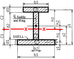
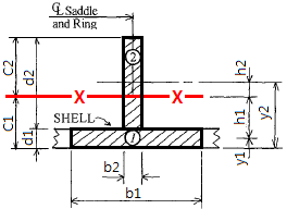
| 43 | Actual inertia moment of Saddle Ring | Ig_Saddle = | 2247612.0 | 2746960.0 | 3246307.0 | 3246307.0 | 603778.0 | 635799.0 | 635799.0 | 966541.0 | 981052.0 | 1027569.0 | 1689587.0 | 111562.0 | 2315248.0 | 2611410.0 | 2746960.0 | 3246307.0 | 2746960.0 | 3246307.0 | cm4 |
| 44 | Saddle Ring (Qty)
Saddle Ring (Size) | SRqty =
SIZE = | 2 S/Rings
T1300x32+430x32 | 2 S/Rings
T1350x32+450x32 | 2 S/Rings
T1400x34+470x34 | 2 S/Rings
T1400x34+470x34 | 2 S/Rings
T900x25+350x25 | 2 S/Rings
T900x25+350x25 | 2 S/Rings
T900x25+350x25 | 2 S/Rings
T1000x30+400x30 | 2 S/Rings
T1000x30+400x30 | 2 S/Rings
T1000x30+400x30 | 2 S/Rings
T1200x30+400x30 | 2 S/Rings
T600x22+300x22 | 2 S/Rings
T1300x32+430x32 | 2 S/Rings
T1350x32+450x32 | 2 S/Rings
T1350x32+450x32 | 2 S/Rings
T1400x34+470x34 | 2 S/Rings
T1350x32+450x32 | 2 S/Rings
T1400x34+470x34 | Rings |
| 45 | Vacuum Ring (Qty)
Vacuum Ring (Size) | VRqty =
SIZE = | 6 V/Rings
T350x15+200x15 | 7 V/Rings
T350x15+200x15 | 7 V/Rings
T400x20+250x15 | 8 V/Rings
T400x20+250x15 | 7 V/Rings
T300x15+100x15 | 7 V/Rings
T300x15+100x15 | 9 V/Rings
T300x15+100x15 | 9 V/Rings
T300x15+100x15 | 10 V/Rings
T300x15+100x15 | 8 V/Rings
T300x15+100x15 | 6 V/Rings
T300x15+100x15 | 2 V/Rings
FB150x20 | 8 V/Rings
T350x15+200x15 | 10 V/Rings
T350x15+200x15 | 9 V/Rings
T350x15+200x15 | 8 V/Rings
T400x20+250x15 | 9 V/Rings
T350x15+200x15 | 8 V/Rings
T400x20+250x15 | Rings |
| 46 | Vacuum Ring @pitch | VR_pitch = | @3050×5
+2×1005 | @2760×6
+2×985 | @3030×6
+2×1005 | @2890×7
+2×1000 | @2800×6
+2×985 | @2920×6
+2×10¹⁰ | @2810×8
+2×10¹⁵ | @3160×8
+2×980 | @3060×9
+2×10²⁰ | @2900×7
+2×1000 | @2850×5
+2×1005 | @2720×1
+2×1000 | @3180×7
+2×990 | @2860×9
+2×990 | @2900×8
+2×980 | @2890×7
+2×1000 | @3170×8
+2×1005 | @3180×7
+2×1005 | mm |
| 47 | Required inertia moment of Stiff. Ring
Ix = 0.18 * D * Pe_MPa * L * Ds² / E ×10E-5 | Ix = | 16661.1 | 24875.5 | 28120.2 | 28120.2 | 6065.3 | 7363.2 | 7363.2 | 8076.4 | 8831.1 | 10485.7 | 14389.8 | 386.6 | 19154.4 | 20492.0 | 24875.5 | 28120.2 | 24875.5 | 28120.2 | cm4 |
| 48 | Actual inertia moment of Vacuum Ring | Ig = | 51158.3 | 54435.3 | 91531.7 | 91531.7 | 21474.2 | 22248.9 | 22248.9 | 22616.6 | 22827.9 | 23515.9 | 24792.1 | 1497.3 | 52130.0 | 52724.3 | 54435.3 | 91531.7 | 54435.3 | 91531.7 | cm4 |
| 49 | Ix / Ig < 1.0 OK | | 0.3 | 0.5 | 0.3 | 0.3 | 0.3 | 0.3 | 0.3 | 0.4 | 0.4 | 0.4 | 0.6 | 0.3 | 0.4 | 0.4 | 0.5 | 0.3 | 0.5 | 0.3 | |
| 50 | Weight Summary | | | | | | | | | | | | | | | | | | | | |
| 51 | 1) Shell Weight | wShell = | 192.605 | 266.019 | 313.661 | 343.702 | 107.284 | 128.494 | 158.863 | 186.675 | 211.355 | 180.937 | 165.698 | 6.744 | 288.855 | 343.884 | 356.758 | 343.702 | 386.757 | 373.801 | ton |
| 52 | 2) Head Weight | wHead = | 57.097 | 85.231 | 96.334 | 96.334 | 21.501 | 26.043 | 26.043 | 28.535 | 31.181 | 36.955 | 49.323 | 1.553 | 65.649 | 70.228 | 85.231 | 96.334 | 85.231 | 96.334 | ton |
| 53 | 3) Saddle Rins(Inside) | WsaddleRing = | 41.074 | 51.11 | 57.65 | 57.65 | 18.057 | 19.973 | 19.973 | 25.127 | 26.014 | 28.084 | 35.028 | 3.934 | 43.543 | 46.118 | 51.11 | 57.65 | 51.11 | 57.65 | ton |
| 54 | 4) Vacuum Rings(Inside) | WvacuumRing = | 13.024 | 17.903 | 25.176 | 28.596 | 7.25 | 7.894 | 10.092 | 11.04 | 12.495 | 10.654 | 9.302 | 0.69 | 17.74 | 22.682 | 22.52 | 28.596 | 22.52 | 28.596 | ton |
| 55 | 5) Swash Bulk Head and Attachment | WbulkHead = | 31.449 | 39.744 | 42.643 | 42.643 | 17.994 | 20.333 | 20.333 | 21.338 | 22.241 | 24.378 | 28.982 | 4.918 | 33.862 | 35.186 | 39.744 | 42.643 | 39.744 | 42.643 | ton |
| 56 | 6) Saddle(CS/Bottom) | Wsaddle_CS = | 29.574 | 48.879 | 57.18 | 57.18 | 12.109 | 13.883 | 13.883 | 14.954 | 16.025 | 18.561 | 25.059 | 1.482 | 34.751 | 37.749 | 48.879 | 57.18 | 48.879 | 57.18 | ton |
| 57 | 7) Accessory(CS/PlatForm) | Waccy_CS = | | | | | | | | | | | | | | | | | | | ton |
| 58 | 8) PUF ( Insulation ) Winsu = Vinsu * Density [ 40 kg/m³] | Winsu = | 15.591 | 19.482 | 21.682 | 23.014 | 10.694 | 11.913 | 14.027 | 15.751 | 17.372 | 15.124 | 14.083 | 1.405 | 20.624 | 23.278 | 23.645 | 23.014 | 25.033 | 24.347 | Ton |
| 59 | Empty Steel Weight(1~7) | Wempty = | 380.414 | 528.368 | 614.326 | 649.119 | 194.889 | 228.533 | 263.214 | 303.42 | 336.683 | 314.693 | 327.475 | 20.726 | 505.024 | 579.125 | 627.887 | 649.119 | 659.274 | 680.551 | Ton |
| 60 | at Operating Condition | Woper = | 994.25 | 1420.35 | 1657.1 | 1775.45 | 497.1 | 591.8 | 710.2 | 828.55 | 946.9 | 852.2 | 852.2 | 22.5 | 1420.35 | 1657.1 | 1775.45 | 1775.45 | 1893.8 | 1893.8 | Ton |
| 61 | at Hydrostatic-test Condition | Wtest = | 2100.0 | 3000.0 | 3500.0 | 3750.0 | 1050.0 | 1250.0 | 1500.0 | 1750.0 | 2000.0 | 1800.0 | 1800.0 | 47.5 | 3000.0 | 3500.0 | 3750.0 | 3750.0 | 4000.0 | 4000.0 | Ton |
| 62 | Dynamic Pressure due to Ship mortion) | PgdMax = | | | | | | | | | | | | | | | | | | | bar.g |
| 63 | Surface Area Calculation for Net Weight | | | | | | | | | | | | | | | | | | | | |
| 64 | Shell Plate Surface Area (OD 기준) | suf_Shell = | | | | | | | | | | | | | | | | | | | m2 |
| 65 | Head Plate Surface Area (OD 기준) | suf_Head = | | | | | | | | | | | | | | | | | | | m2 |
| 66 | | | | | | | | | | | | | | | | | | | | | |
| 67 | | | | | | | | | | | | | | | | | | | | | |
| 68 | | | | | | | | | | | | | | | | | | | | | |
| 69 | Surface Area Total | SArea | | | | | | | | | | | | | | | | | | | m2 |
| Weight Summary | [조 회] | [조 회] | [조 회] | [조 회] | [조 회] | [조 회] | [조 회] | [조 회] | [조 회] | [조 회] | [조 회] | [조 회] | [조 회] | [조 회] | [조 회] | [조 회] | [조 회] | [조 회] | Unit |
| 1. Cylindrical Shell Plate | at Operation
t (mm) | at Test
(mm) | c1 (mm) | c2 (mm) | Tu (mm) | SKETCH
ASME SEC.VIII Div.1 |
| | KR (한국선급) | | 11.482 | 11.65 | 0.52 | 0 | 12.00 | 
|
| LR (영국선급) | | T = | P · Rj
10 · σ · J - 0.5 · P |
| + 0.75 |
| 11.475 | 11.55 | 0.53 | 0 | 12.00 |
| DNV-GL(노르웨이) | | 11.402 | 11.64 | 0.6 | 0 | 12.00 |
| Class-Nk(일본선급) | | 11.475 | 11.64 | 0.53 | 0 | 12.00 |
| BV (프랑스) | | 11.475 | 11.64 | 0.53 | 0 | 12.00 |
| ABS (미국선급) | | 11.475 | 11.64 | 0.53 | 0 | 12.00 |
| ASME SEC.VIII-Div.1(압력용기) | | 11.482 | 11.65 | 0.52 | 0 | 12.00 |
| ASME SEC.VIII-Div.2(압력용기) | | t = | | · [exp(P / SE) - 1] + CA |
| 11.475 | 11.64 | 0.53 | 0 | 12.00 |
| 2. [HH] Hemi-Spherical Head | at Operation
t (mm) | at Test
(mm) | c1 (mm) | c2 (mm) | Tu (mm) | SKETCH
ASME SEC.VIII Div.1 |
| | KR (한국선급) | | 6.223 | 5.80 | 0.78 | 0 | 7.00 |  |
| LR (영국선급) | | T = | P · Rj
20 · σ · J - 0.5 · P |
| + 0.75 |
| 6.228 | 5.79 | 0.77 | 0 | 7.00 |
| DNV-GL(노르웨이) | | 6.210 | 5.81 | 0.79 | 0 | 7.00 |
| Class-Nk(일본선급) | | 6.228 | 5.81 | 0.77 | 0 | 7.00 |
| BV (프랑스) | | 6.237 | 5.82 | 0.76 | 0 | 7.00 |
| ABS (미국선급) | | 6.228 | 5.81 | 0.77 | 0 | 7.00 |
| ASME SEC.VIII-Div.1(압력용기) | | 6.223 | 5.80 | 0.78 | 0 | 7.00 |
| ASME SEC.VIII-Div.2(압력용기) | | t = | | · [exp(0.5P/SE) - 1] + CA |
| 6.228 | 5.81 | 0.77 | 0 | 7.00 |
| 3. [EE] 2:1 Ellipsoidal Head | at Operation
t (mm) | at Test
(mm) | c1 (mm) | c2 (mm) | Tu (mm) | SKETCH
ASME SEC.VIII Div.1 |
| | KR (한국선급) | | 13.162 | 13.35 | 0.84 | 0 | 14.00 | 
UG-32 FORMED HEADS, AND SECTIONS, PRESSURE ON CONCAVE SIDE
(c) Ellipsoidal Heads With ts/L ≥ 0.002
(d) Torispherical Heads With t s /L ≥ 0.002.
위 수식을 사용하기 위한 필수 조건임
( 2:1 Ellipsoidal head and Dish Head 필수조건 임 )
ts / L ≥ 0.002
tsMin = 0.002 * L + CA = 7 mm |
| LR (영국선급) | | 15.614 | 15.95 | 0.89 | 0 | 16.50 |
| DNV-GL(노르웨이) | | 15.353 | 15.95 | 0.65 | 0 | 16.00 |
| Class-Nk(일본선급) | | 11.457 | 11.62 | 0.9 | 0.14 | 12.50 |
| BV (프랑스) | | 18.223 | 19.14 | 0.78 | 0 | 19.00 |
| ABS (미국선급) | | 11.446 | 11.61 | 0.9 | 0.15 | 12.50 |
| ASME SEC.VIII-Div.1(압력용기) | | 11.446 | 11.61 | 0.9 | 0.15 | 12.50 |
| ASME SEC.VIII-Div.2(압력용기) | | 11.446 | 11.61 | 0.9 | 0.15 | 12.50 |
| 4. [DD] 10% Dish Head | at Operation
t (mm) | at Test
(mm) | c1 (mm) | c2 (mm) | Tu (mm) | SKETCH
ASME SEC.VIII Div.1 |
| | KR (한국선급) | | T = [ | | + c ] × 1.15, E=1.5406 |
| 22.412 | 23.63 | 0.59 | 0 | 23.00 | 
UG-32 FORMED HEADS, AND SECTIONS, PRESSURE ON CONCAVE SIDE
(c) Ellipsoidal Heads With ts/L ≥ 0.002
(d) Torispherical Heads With t s /L ≥ 0.002.
위 수식을 사용하기 위한 필수 조건임
( 2:1 Ellipsoidal head and Dish Head 필수조건 임 )
ts / L ≥ 0.002
tsMin = 0.002 * L + CA = 7 mm |
| LR (영국선급) | | 25.530 | 26.67 | 0.9 | 0.07 | 26.50 |
| DNV-GL(노르웨이) | | 25.008 | 26.67 | 0.9 | 0.09 | 26.00 |
| Class-Nk(일본선급) | | 17.109 | 17.90 | 0.89 | 0 | 18.00 |
| BV (프랑스) | | 25.008 | 26.67 | 0.9 | 0.09 | 26.00 |
| ABS (미국선급) | | 17.092 | 17.88 | 0.9 | 0.01 | 18.00 |
| ASME SEC.VIII-Div.1(압력용기) | | t = | | + CA, L=1.0·D, M=1.5406 |
| 17.092 | 17.88 | 0.9 | 0.01 | 18.00 |
| ASME SEC.VIII-Div.2(압력용기) | | t = | | + CA, L=1.0·D, M=1.5406 |
| 17.092 | 17.88 | 0.9 | 0.01 | 18.00 |
| | Where, |
| Inside Diameter (Shell, Head) | D = | 3000 | mm | 3.000 | m |
| Inside Radius (Shell, Head ) | R = | 1500 | mm | 1.500 | m |
| Min. Tensile Stress (Weld Metal) | Rm = | 515 | MPa | | |
| Min. Yield Stress (Weld Metal) | Re = | 205 | MPa | | |
| Allowbale Membrane Stress, f = Min(660/3.5, 400/1.5) | f = | 136.66 | MPa | | |
| at Ship Operation Condition |
| Design Pressure, P = Po + Pgd(max) | P = | 0.951 | MPa | 9.51 | bar.g |
| Allowbale Membrane Stress, f = Min(660/3.5, 400/1.5) | f = | 136.66 | MPa | | |
| Corrosion Allowance | CA = | 1.0 | mm | | |
| at Hydrostatic-Test Condition |
| Hydrostatic-test Pressure, P = Poper * 1.5 | P = | 1.4265 | MPa | 14.265 | bar.g |
| Allowbale Stress, f = 0.9 * Rm | f = | 184.5 | MPa | | |
| Corrosion Allowance | CA = | 0.00 | mm | | |
|
12. Tank Capacity : 47.5 m³
Head Type ; [HH] Spherical-Head | Tank Size : ø3000 x 4720 (L = 7720 mm ) | Plate 발주폭(Max) : 3400 mm
Head Plate Surface Area(표면적) : 28.274 m² | Head Type ;
[HH] Spherical-Head |
| No. | Name | MATERIAL | SIZE
t x W X L (mm) | Quantity
(SHT) | Weight
(kg) | 표면적
m²/ pcs | Remark | SKETCH |
| 1 | Shell Plate (Saddle Support Part) | SA240-304 | 14.50 | 2,410 | 9,471 | 2 | 5,196 | 22.82511 | 원주분할: L=π×ø3014.5 = 9470mm / 1분할= 9471mm | 

|
| 2 | Shell Plate (Dome Reinforcement) | SA240-304 | 14.50 | 3,400 | 4,000 | 1 | 1,548 | 13.60000 | Dome Part |
| 3 | [HH] Hemi-Head Plate (Side) | SA240-304 | 7.00 | 2,362 | 1,580 | 8 | 1,207 | 21.97328 | Angle = (#4WP: 51º, CP : 60.204º) [deg] |
| 4 | [HH] Hemi-Head Plate (Center) | SA240-304 | 7.00 | 2,047 | 2,047 | 2 | 346 | 6.30105 | Angle = (#4WP: 51º + 39º : #5WP,CP) = 90º [deg] |
| 5 | Wear Plate and 지지금구(Fix / Sliding) | SA240-304 | 14.50 | 1,200 | 4,781 | 2 | 1,306 | 5.73720 | For Saddle Support |
| 6 | SWASH Bulk Head ( Baffle Plate - Hole 중량 포함 ) | SA240-304 | 10.00 | 1,910 | 2,700 | 2 | 810 | 5.15700 | Baffle Plate Net Surface Area = 4.34919 m²(Hole 면적포함) |
| 7 | Bulk Head (Baffle Stiffener Plate) | SA240-304 | 15.00 | 1,200 | 4,783 | 2 | 1,352 | 5.73960 | 10 |
| 8 | Bulk Head (U-BAND Spring : 충격완화금구) | SA240-304 | 25.00 | 400 | 660 | 28 | 1,451 | 0.26400 | |
| 9 | Vacuum Ring (FB150x20) | SA240-304 | 20.00 | 150 | 0 | 1 | 211 | 1.34300 | A = π× (OD 3000²- ID : 2700²) / 4 = 1.343 m² |
| 10 | Saddle Ring (Rib) | SA240-304 | 22.00 | 200 | 578 | 24 | 479 | 0.11560 | |
| 11 | Saddle Ring (Web) T600x22+300x22 | SA240-304 | 22.00 | 578 | 0 | 2 | 1,519 | 4.39800 | A = π× (OD 3000²- ID : 1844²) / 4 = 4.398 m² |
| 12 | Saddle Ring (Flange) T600x22+300x22 | SA240-304 | 22.00 | 300 | 7,609 | 2 | 788 | 2.28270 | L = π × (ø2422 ) = 7609 mm |
| 13 | Saddle Ring (Rib Plate) | SA240-304 | 22.00 | 139 | 556 | 24 | 320 | 0.07728 | |
| 14 | Saddle Support (Base Plate) | DH32 OR A516-60 | 25.00 | 760 | 4,800 | 2 | 1,432 | 3.64800 | Base Plate : t25 mm |
| 15 | Saddle Support (Rib & Etc) | DH32 OR A516-60 | 19.00 | 3,048 | 110 | 1 | 50 | 0.33528 | Rib Plate Thick. J=19.0 (mm) , tg=19.0 (mm) |
| [ONLY] Shell and head Plate Quentity | 13 sht | | | | |
| Total Weight | | 18,015 | kg | | |
| 번호 | 0
sid | 1
headType | 2
jNo | 3
rNo | 4
DESCR | 5
SYMBOL | 6
VALUE | 7
UNIT |
| 1 | 2 | 0 | 11 | 1 | TANK In-Diameter | Di = | 3000.0 | mm |
| 2 | 2 | 0 | 11 | 2 | Hemi-Spherical Depth | z = 0.5*D | 1500.0 | mm |
| 3 | 2 | 0 | 11 | 3 | Cylinder Straight Length (TL to TL : 10mm 단위올림) | TL = | 4720.0 | mm |
| 4 | 2 | 0 | 11 | 4 | Total Length ( Head End to End ), L = 2*z +TL | L = | 7720.0 | mm |
| 5 | 2 | 0 | 11 | 5 | Design Liquid Level | DLL = | 2665.0 | mm |
| 6 | 2 | 0 | 11 | 6 | | | 0.0 | |
| 7 | 2 | 0 | 11 | 7 | Gross Volume, Vnom = Vcyl+Vhead | Vnom = | 47.5 | m³ |
| 8 | 2 | 0 | 11 | 8 | Net Volume ( Vnet = 0.98*Vnom) | Vnet = | 45.0 | 0.98*Vnom |
| 9 | 2 | 0 | 11 | 9 | Vhead = πD³ / 6 | Vhead = | 14.1 | m³ |
| 10 | 2 | 0 | 11 | 10 | Vcyl = πD² / 4 * L | Vcyl = | 33.4 | m³ |
| 11 | 2 | 0 | 11 | 11 | Storage Ratio = Vnet / Vnom * 100 | Sratio = | 94.69 | % |
| 12 | 2 | 0 | 11 | 12 | Static Head Pressure, Ps = ρgh(h=DLL) | Ps = | 0.0131 | MPa |
| 13 | 2 | 0 | 11 | 13 | [ASME] Total Design Pressure, P = Po+Ps | P_ASME = | 0.9641 | MPa |
| 14 | 2 | 0 | 11 | 14 | [ASME] Cylinder Shell Thickness | t_Cyl = | 11.63 | mm |
| 15 | 2 | 0 | 11 | 15 | [ASME] Hemi-Spherical Head Thickness | t_HHead = | 6.29 | mm |
| 16 | 2 | 0 | 11 | 16 | [ASME] Cylinder Shell Thk (Vacuum Ring Pitch: 3.5m ) | t_CylPe = | 9.0 | mm |
| 17 | 2 | 0 | 11 | 17 | [ASME] Allowable External Pressure(Shell), Pe < Pa_Cyl | Pa_Cyl = | 0.0544 | MPa |
| 18 | 2 | 0 | 11 | 18 | [ASME] Allowable External Pressure(Head ), Pe < Pa_Head | Pa_Head = | 0.1494 | MPa |
| 19 | 2 | 0 | 11 | 19 | [Class] Dynamic Pressure(Ship Motion) | Pgd(max) = | 0.1331 | MPa |
| 20 | 2 | 0 | 11 | 20 | [Class] Total Design Pressure, P = Po+Pgd(max) | P_Class = | 0.951 | MPa |
| 21 | 2 | 0 | 11 | 21 | [Class] Cylinder Shell Thickness | t_Cyl = | 11.48 | mm |
| 22 | 2 | 0 | 11 | 22 | [Class] Hemi-Spherical Head Thickness | t_HHead = | 6.22 | mm |
| 23 | 2 | 0 | 11 | 23 | [LR] Cylinder Shell Thk (Vacuum Ring: 3.5m ) | t_CylPe = | 9.0 | mm |
| 24 | 2 | 0 | 11 | 24 | [DNV-GL] Hemi-Spherical Head Thk (For Vacuum )
Pc=2.4*Et*(t-c/Ro)²/ 3.7 [DNV-GL Pt4-Ch7] | t_HeadPe = | 2.7 | mm |
| 25 | 2 | 0 | 11 | 25 | [LR] Allowable External Pressure (Shell DNV-GL, LR, GV) | Pcr = | 0.0504 | MPa |
| 26 | 2 | 0 | 11 | 26 | [NK] Allowable External Pressure (ClassNk equal ASME Div2. ) | Pa_div2 = | 0.1622 | MPa |
| 27 | 2 | 0 | 11 | 27 | PUF Insulation Volume | Vinsu = | 35.12 | m³ |
| 28 | 2 | 0 | 11 | 28 | Min. Thickness for Internal Pressure
tMinPo(DNV-GL) = 3+Di/1500+CA | tMinPo = | 6.0 | mm |
| 29 | 2 | 0 | 11 | 29 | Min. Thickness for Internal Pressure, (IGC_LR_ASME) | tMinBase = | 3.0 | mm |
| 30 | 2 | 0 | 11 | 30 | Min. Thickness for External Pressure, tMinPe = Do/850
ASME SECTION II, PART D - SUBPART 3 (METRIC), FIG. G | tMinPe = | 4.53 | mm |
| 31 | 2 | 0 | 11 | 31 | | | 0.0 | |
| 32 | 2 | 0 | 11 | 32 | [Calc] Shell Thickness | tCyl = | 11.63 | mm |
| 33 | 2 | 0 | 11 | 33 | [Calc] Head Thickness | tHead = | 6.29 | mm |
| 34 | 2 | 0 | 11 | 34 | Nominal Shell Thickness (벤딩마진포함) | tu_Cyl = | 12.5 | mm |
| 35 | 2 | 0 | 11 | 35 | Nominal Head Thickness (성형마진포함) | tu_Head = | 7.0 | mm |
| 36 | 2 | 0 | 11 | 36 | Shell Thickness Margin, tMarginCyl = tuCyl - tCyl | tMarginCyl = | 0.87 | mm |
| 37 | 2 | 0 | 11 | 37 | Head Thickness Margin, tMarginHead = tuHead - tHead | tMarginHead = | 0.71 | mm |
| 38 | 2 | 0 | 11 | 38 | | | 0.0 | |
| 39 | 2 | 0 | 11 | 39 | | | 0.0 | |
| 40 | 2 | 0 | 11 | 40 | Shell Segment 수량 | sQty = | 2.0 | sheets |
| 41 | 2 | 0 | 11 | 41 | Shell Segment Width | sWidth = | 2410.0 | mm |
| 42 | 2 | 0 | 11 | 42 | Shell Cutting Plan Length, @SegmentWidth * sQty= | cpLength = | 0.0 | mm |
| 43 | 2 | 0 | 11 | 43 | Actual inertia moment of Saddle Ring | Ig_Saddle = | 111562.0 | cm4 |
| 44 | 2 | 0 | 11 | 44 | Saddle Ring (Qty)
Saddle Ring (Size) | SRqty =
SIZE = | 0.0 | Rings |
| 45 | 2 | 0 | 11 | 45 | Vacuum Ring (Qty)
Vacuum Ring (Size) | VRqty =
SIZE = | 1.0 | Rings |
| 46 | 2 | 0 | 11 | 46 | Vacuum Ring @pitch | VR_pitch = | 2720.0 | mm |
| 47 | 2 | 0 | 11 | 47 | Required inertia moment of Stiff. Ring
Ix = 0.18 * D * Pe_MPa * L * Ds² / E ×10E-5 | Ix = | 386.6 | cm4 |
| 48 | 2 | 0 | 11 | 48 | Actual inertia moment of Vacuum Ring | Ig = | 1497.3 | cm4 |
| 49 | 2 | 0 | 11 | 49 | Ix / Ig < 1.0 OK | | 0.3 | |
| 50 | 2 | 0 | 11 | 50 | Weight Summary | | 0.0 | |
| 51 | 2 | 0 | 11 | 51 | 1) Shell Weight | wShell = | 6.744 | ton |
| 52 | 2 | 0 | 11 | 52 | 2) Head Weight | wHead = | 1.553 | ton |
| 53 | 2 | 0 | 11 | 53 | 3) Saddle Rins(Inside) | WsaddleRing = | 3.934 | ton |
| 54 | 2 | 0 | 11 | 54 | 4) Vacuum Rings(Inside) | WvacuumRing = | 0.69 | ton |
| 55 | 2 | 0 | 11 | 55 | 5) Swash Bulk Head and Attachment | WbulkHead = | 4.918 | ton |
| 56 | 2 | 0 | 11 | 56 | 6) Saddle(CS/Bottom) | Wsaddle_CS = | 1.482 | ton |
| 57 | 2 | 0 | 11 | 57 | 7) Accessory(CS/PlatForm) | Waccy_CS = | 0.0 | ton |
| 58 | 2 | 0 | 11 | 58 | 8) PUF ( Insulation ) Winsu = Vinsu * Density [ 40 kg/m³] | Winsu = | 1.405 | Ton |
| 59 | 2 | 0 | 11 | 59 | Empty Steel Weight(1~7) | Wempty = | 20.726 | Ton |
| 60 | 2 | 0 | 11 | 60 | at Operating Condition | Woper = | 22.5 | Ton |
| 61 | 2 | 0 | 11 | 61 | at Hydrostatic-test Condition | Wtest = | 47.5 | Ton |
| 62 | 2 | 0 | 11 | 62 | Dynamic Pressure due to Ship mortion) | PgdMax = | 0.0 | bar.g |
| 63 | 2 | 0 | 11 | 63 | Surface Area Calculation for Net Weight | | 0.0 | |
| 64 | 2 | 0 | 11 | 64 | Shell Plate Surface Area (OD 기준) | suf_Shell = | 0.0 | m2 |
| 65 | 2 | 0 | 11 | 65 | Head Plate Surface Area (OD 기준) | suf_Head = | 0.0 | m2 |
| 66 | 2 | 0 | 11 | 66 | | | 0.0 | |
| 67 | 2 | 0 | 11 | 67 | | | 0.0 | |
| 68 | 2 | 0 | 11 | 68 | | | 0.0 | |
| 69 | 2 | 0 | 11 | 69 | Surface Area Total | SArea | 0.0 | m2 |
]