BOR Calculation (IMO TYPE C FUEL TANK)
API 650 Sherical Tank EN14620 ALLOWABLE STRESS SADDLE °è»ê¼­BOG °è»ê¼­BOG Each
API 620 °­µµ°è»êVolume Calculation Formulmya[PDF] Vessel Volume Calculator LNGFuelTank.html[³í¹® »çº»] LNGFuelTank[³í¹® ¿øº»]

NoDescriptionSymbol ValueUnit
1Fluid NameFluid =
2Contents(LNG) TemperatureTi =¡É
3Outer Surface TemperatureTo =¡É
4Temperature difference ¡âT =To-Ti¡âT =¡É
5Effective Area of Inner BaseA =m©÷
9[Design Data] Net Storage Capacity (Vnom * 90%)V =m©ø
13Density of LNG (by P.O.S)¥ñ =kg/m©ø
12Latent heat of vaporization of LNG(Áõ¹ßÀá¿­) by P.O.Sh =J / kg
14Content Weight of LNG (ÃÑÁú·®), F = V * ¥ñF =kg
15(POS) Boil Off Rate per DayBOR(POS)=%/day
CALC! [BOG °è»ê ½ÇÇà]
´ë·ù ¿­Àü´Þ : ´ë¸¸ (ÇÊÁî ¿£Áö´Ï¾î¸µ) BEDD 17 - NVLNG-ITECO-FD-SA-CAL-100_Sizing Calculation LNG Tank_Rev.3.pdf
Âü°í1 : Vapour to Roof ( ´ë·ù : Suspended Deck ), h = 22 W/(m©÷¡¤¡É)
Âü°í2 : Roof Plate to Air ( ´ë·ù : ), h = 68 W/(m©÷¡¤¡É)
Âü°í3 : Liquid to Shell Side ( ´ë·ù ) , h = 3500 W/(m©÷¡¤¡É)
Âü°í4 : Outer Shell Plate to Air ( ´ë·ù ), h = 68 W/(m©÷¡¤¡É)
Âü°í5 : Liquid to Bottom Plate ( ´ë·ù ) , h = 3500 W/(m©÷¡¤¡É)
Âü°í6 : Under the Concrete slab to Air ( ´ë·ù : ), h = 45 W/(m©÷¡¤¡É)

No.Insulation Material
Location :  
Symbolº¸³ÃÀç µÎ²²
t
¿­Àüµµµµ
k
Film Coeff.
h
R = t/k
OR
R = 1/h
Temperature
Difference
¥ät=¡âT ¡¤ (R/¢²R)
Face
Temperature
RemarkSKETCH
mW /(m¡¤¡É)W/(m©÷¡¤¡É)(m©÷¡¤¡É) / W¡É¡É
1          
0.00029
0.0038
-168.00
2          
0.00017
0.0022
-167.99
3          
0.03125
0.4125
-167.58
4          
0.00017
0.0022
-167.58
5          
0.03125
0.4125
-167.17
6          
0.00000
0.0000
0.00
7          
3.77358
49.8150
-117.35
8          
3.32226
43.8571
-73.49
9          
2.91545
38.4868
-35.01
10          
2.57069
33.9357
-1.07
11          
0.12500
1.6501
0.58
12          
0.00025
0.0033
0.58
13          
0.31250
4.1253
4.71
14          
0.02222
0.2934
5.00
15          
0.00000
0.0000
0.00
16          
0.00000
0.0000
0.00
17          
0.00000
0.0000
0.00
18          
0.00000
0.0000
0.00
19          
0.00000
0.0000
0.00
20          
0.00000
0.0000
0.00
Total Wall Thickness, Thk = ¢²tThk =1.215
Total Thermal Resistance Ratio, ¢²R

(Àüü ¿­ÀúÇ×À²)
¢²R =13.105
CALC! [BOG °è»ê ½ÇÇà]

Result
No.Insulation MaterialSymbolº¸³ÃÀç µÎ²²
t
¿­Àüµµµµ
k
Film Coeff.
h
R = t/k
OR
R = 1/h
Temperature
Difference
¥ät=¡âT ¡¤ (R/¢²R)
Face
Temperature
Remark
mW /(m¡¤¡É)W/(m©÷¡¤¡É)(m©÷¡¤¡É) / W¡É¡É
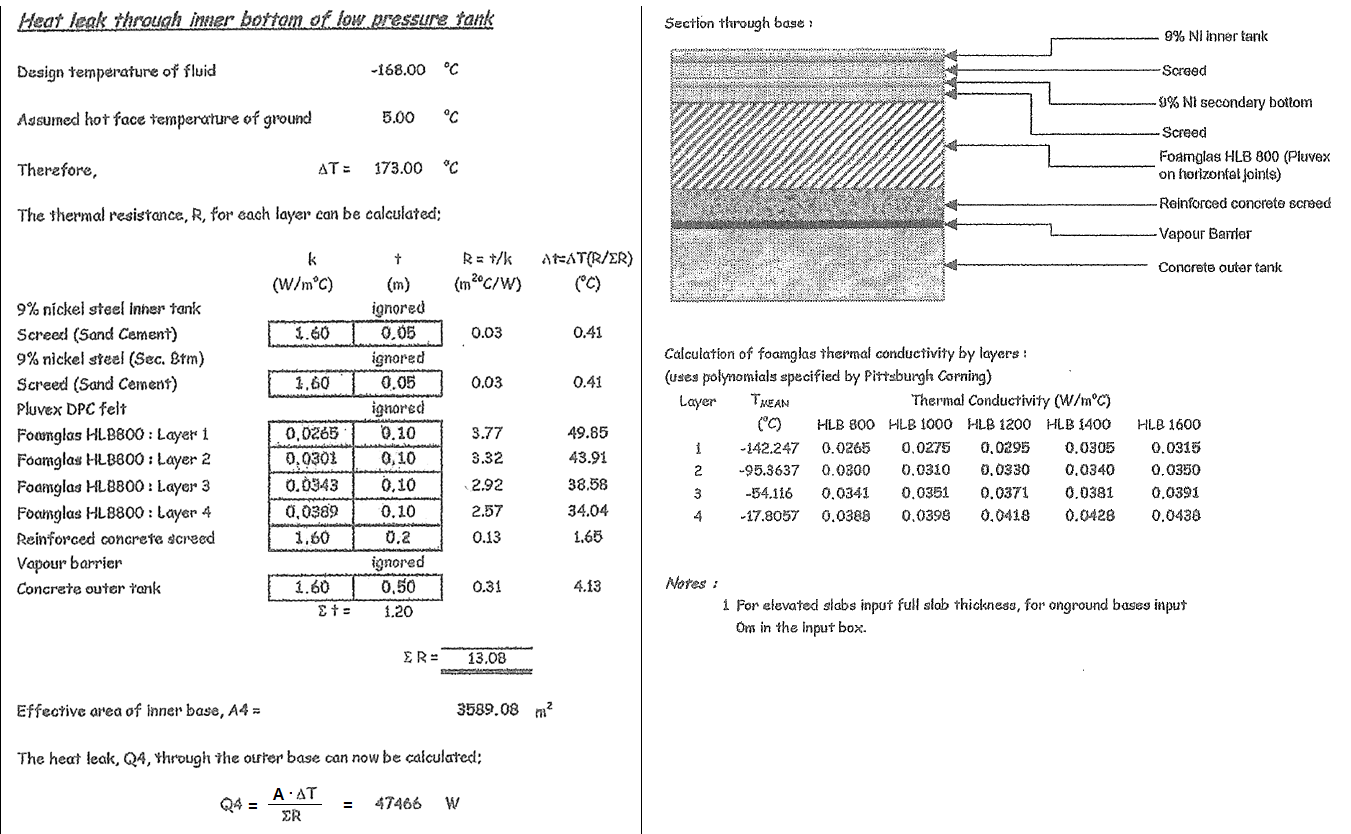
1Liquid to Bottom Shell (Convection)35000.000290.0038-168.00
29% Nickel Steel (inner tank)ignored0.00530.00.000170.0022-167.99
3Screed ( Sand Cement )0.0501.60.031250.4125-167.58
49% Nickel Steel (2nd Bottom)ignored0.00530.00.000170.0022-167.58
5Screed ( Sand Cement )0.0501.60.031250.4125-167.17
6BDPC Felt (Pluvex DPC Felt)ignored0.000000.00000.00
7Form Glass HLB 800 : Layer 1at -142.247 ¡É0.1000.02653.7735849.8150-117.35
8Form Glass HLB 800 : Layer 2at -95.3637 ¡É0.1000.03013.3222643.8571-73.49
9Form Glass HLB 800 : Layer 3at -54.116 ¡É0.1000.03432.9154538.4868-35.01
10Form Glass HLB 800 : Layer 4at -17.8057 ¡É0.1000.03892.5706933.9357-1.07
11Reinforced Concrete Screed0.2001.60.125001.65010.58
12Vapour Barrier ( 3rd Btm Steel ? )ignored0.00520.00.000250.00330.58
13Concrete Outer Tank0.5001.60.312504.12534.71
14Air to Concrete (Convection)ignored450.022220.29345.00
Total Wall Thickness, Thk = ¢²tThk =1.215
Total Thermal Resistance Ratio, ¢²R
(Àüü ¿­ÀúÇ×À²)
¢²R =13.105(m©÷¡¤¡É) / W
BOG Calculation Result :
No.DescriptionSI UnitMetric
1Contents(LNG) TemperatureTi =-168¡ÉTi =105.15K
1Outer Surface TemperatureTo =5¡ÉTo =278.15K
1Temperature difference ¡âT =To-Ti¡âT =173¡É¡âT =173K
2Effective Insulation AreaA =3589.08m©÷A =3589.08m©÷
3Overall heat transfer coefficient, U = 1 / ¢²RU =0.07631W / (m©÷¡¤¡É)U =0.06561kcal / (m©÷¡¤K)
4Total Heat Leak(¹æ»ê¿­·®) Q = U¡¤¡âT¡¤AQ =47379.4WQ =40766.2kcal / hr
5Heat Flex(¿­À¯¼Ó) q = ¡âT / ¢²R or Q / Aq =13.201W / m©÷q =11.3508kcal / (hr¡¤m©÷)
9Latent heat of vaporization of LNG(Áõ¹ßÀá¿­) by P.O.Sh =511000J / kgL =122.05kcal / kg
10[Design Data] Net Storage Capacity (90%)V =475.35m©øV =475.35m©ø
11Density of LNG (by P.O.S)¥ñ =425kg / m©ø¥ñ =425kg / m©ø
12Content Weight of LNG (ÃÑÁú·®), F = V ¥ñF =202024kgF =202024kg
29Heat Leak Weight per one hour
(½Ã°£´ç ¿­¼Õ½ÇÁß·®), Wt = 3600 Q / h
Wt =333.7883kg / hrWt =333.7883kg / hr
13(POS) Boil Off Rate per DayBOR(POS)=0.3%/day
14(Calculate) Boil Off Rate per Day
BOR(day) = 243600100 Q / (h F)
BOR(day)=3.9653%/day
15Check, Calcute BOR(day) < BOR(design) NG!
40Leakage Weight per Day, W_loss = F BOR / 100W_loss =8010.92kg/day
41Leakage Volume per Day, V_loss = W_loss / ¥ñ V_loss= 18.8492m©ø/ kg
16Days of Vaporization of Liquid(Evaporation)
, Hdays = F / W_loss
Hdays =25.22day
Where ,
t : Insulation material Thickness, º¸¿ÂµÎ²² (m)
k : Thermal Conductivity ¿­ÀüµµÀ² [W /(m¡¤¡É)]
h : Heat convection coefficients, ´ë·ù¿­Àü´Þ°è¼ö [W/(m©÷¡¤¡É)]
R : Thermal Transfer Resistance, ¿­ÀúÇ×À² (m©÷¡¤¡É)/W


½ÃÀ۽ð£ = [2025-04-03 17:20:12.0973]
Á¾·á½Ã°£ = [2025-04-03 17:20:12.0974]

Referance
1. Thermophysical Properties of Refrigerants(ASHRAE Chap.30 ¹ßÃé)_2009³â.pdf
No.LiquidBoiling Point
Temperature
Latent Heat
of Vaporization
Áõ¹ßÀá¿­
L=h(vapor)-h(liquid)
Density of Liquid
at Boiling Point
ASHRAE NOEnthalpy
(Vapor)
Enthalpy
(Liquid)
(¡É)(K)(KJ / kg)¥ñ , (kg / m©ø)h, (kJ/kg)h, (kJ/kg)
1LNG(CH4 Methane) -163110.15510.83422.4R50510.830
2ÇÁ·ÎÆÇ (Propane)-42.11231.04425.59580.9R290525.95100.36
3ºÎź (Butane)-0.49272.66385.71601.3R600584.58198.87
4ÇÁ·ÎÇÊ·» ( Propylene )-47.69225.46439.16609.1R1270529.390.14
5¾Ï¸ð´Ï¾Æ (Ammonia )-33.33239.821369.5682R7171418.2648.76
7Liquid Oxygen »ê¼Ò-18390.15213.061141.2R73279.69-133.37
6¾×È­Áú¼Ò LN2-195.877.35199.18806.1R72877.16-122.02
8¾Æ¸£°ï-185.887.35161.141395.4R74043.62-117.52
9Çï·ý-268.94.2520.75124.73R70430.599.84
10¾×È­¼ö¼Ò (LH2) (Parahydrogen)-252.820.35443.970.8R702p189.5-254.4


2. Thermal conductivity of Insulation material (¿­Àüµµµµ , k)
No.Insulation MaterialSI UnitMetricDensityPARTREMARK
(ASTM No.)
k [W/m¡¤¡É]k [kcal/h¡¤m¡¤¡É]¥ñ, kg/m©ø
1Steel Shell Plate (C/S)45.2988538.957850Shell & Roof???
2PolyUrethane Foam (PUF)0.0267490.02340Shell & Roof
3Perlite0.0441940.03865Shell & Roof
4Resilient blanket0.0267490.02317.5Shell & Roof
5Pre-stressed concrete2.3004141.978-Shell & Roof
6Cellular glass0.0430310.037120Shell & Bottom
7
8Perlite Concrete Block (PCB)0.270.23221200Bottom
9Level Concrete0.290750.25-Bottom
2Cellular Glass Block0.0372160.032120Bottom
10Dry sand0.1570.135-Bottom
11Level concrete0.290750.25-Bottom
12Fiber Glass0.0407050.03524Roof Deck »ó´Ü


3. Fillm coefficient of heat transfer (°æ¸·¿­Àü´Þ °è¼ö, h)
No.Insulation MaterialSI UnitMetricDensityREMARK
(ASTM No.)
h [W/m©÷¡¤¡É]h [kcal/h¡¤m©÷¡¤¡É]¥ñ, kg/m©ø
1Liquid to Steel23.2620-
2Air to Steel11.6310-
3Air to concreate11.6310-
Where,
  º¸¿ÂµÎ²², t : Insulation Thickness [m]
  (ÃÑ°ý ¿­Àü´Þ °è¼ö) Overall heat transfer coefficient, Us= 1/(t/k) [W/m©÷¡¤¡É]
  (¿­ÀúÇ×) Thermal Resistance , R = t/(k*A) [¡É/W]

4. °æ¸· ¿­Àü´Þ °è¼ö
[ ÌÑدæðîîÓ¹Ìõ⦠, film coefficient of heat transfer , Warmeubergangszahl ]
¹°Ã¼ÀÇ °æ°è¸é¿¡¼­ ¿­Àü´ÞÀ» Áö¹èÇÏ´Â ¿­Àü´Þ °è¼öÀÇ ÀÏÁ¾. °íüº®°ú À¯Ã¼ »çÀÌ¿¡ ¿­Àü´ÞÀÌ ÇàÇØÁö´Â °æ¿ìÀÇ ¿Âµµ ºÐÆ÷´Â,
À¯Ã¼°¡ ¿¹¸¦ µé¸é ³­·ù »óÅ·ΠÈ帣°í ÀÖÀ» ¶§´Â ´ÙÀ½ ±×¸²°ú °°ÀÌ º®¸é °¡±îÀÌ¿¡ ±Þ°ÝÇÑ ¿Âµµ ±â¿ï±â°¡ Á¸ÀçÇÑ´Ù.
ÀÌ°ÍÀº À¯Ã¼ º»Ã¼¿¡¼­´Â º®¸é¿¡ ¼öÁ÷ ¹æÇâÀÇ À¯Ã¼ ÈåÆ®·¯Áü¿¡ ÀÇÇØ ¿­ÀÇ À̵¿ÀÌ À绡¸® ÀÌ·ç¾îÁö´Â µ¥ ´ëÇؼ­ ¾Æ¹«¸® À¯Ã¼ º»Ã¼°¡
³­·ùÀÌ´õ¶óµµ º®¸é °¡±îÀÌ¿¡¼­´Â ÈåÆ®·¯ÁüÀÌ ¾ïÁ¦µÇ°í º® Ç¥¸é¿¡´Â ÃþÈ帧 »óÅÂÀÇ ¾ãÀº À¯Ã¼¸·ÀÌ À־
¿©±â¸¦ Åë°úÇÏ´Â Àüµµ ¿­Àü´ÞÀÇ ÀúÇ×ÀÌ ¸Å¿ì Å©±â ¶§¹®ÀÌ´Ù.

¹øÈ£±¸ºÐh[kcal/h¡¤m¡¤¡É]
1°ø±â °¡¿­, ³Ã°¢1~50
2¹° °¡¿­, ³Ã°¢200~15000
3±â¸§ °¡¿­, ³Ã°¢50~1500
4¼öÁõ±â °ú¿­20~100
5¼öÁõ±â ¸·»ó ÀÀÃà4000~15000
6¼öÁõ±â ¹æ¿ï»ó ÀÀÃà50000~100000
7À¯±â Áõ±â ÀÀÃà1000~2000
8¹° ²úÀ½1500~40000

µ¿¼ºÄɹÌÄ® IMO A/B/C TYPE TANK (PUF INSULATION )

Product Description

Insulation System of PUF SPRAY type applicable to LPG/LEG/LNG liquidified cargi tank
Applicable to DECK TANK due to high environmental effect resistance

Construction is easy, and easy maintenance and repair

Relatively short construction period saves costs

Fp140-40
Properties Unit Allowance Test Method
Sprayed density kg/m©ø 36 – 50 ASTM D1622
Compressive strength kg/cm©÷ ¡Ã 1.7 ASTM D1621
Tensile strength kg/cm©÷ ¡Ã 2.0 ISO 1926:2009
Thermal conductivity at 20¡ÆCW/mK¡Â 0.021ASTM C518
at 20¡ÆC aged 4 month W/mK¡Â 0.023ASTM C518
Dimensional stability vol% ¡Â 1 ASTM 2126
Closed cell content % ¡Ã 90 ASTM D6226
Water absorption g/100cm©÷ ¡Â 3.0 KS M 3809
Flammability B2 DIN 4102, Part 1

Fp140-60
Properties Unit Allowance Test Method
Sprayed density kg/m©ø 50 – 56 ASTM D1622
Compressive strength kg/cm©÷ ¡Ã 2.5 ASTM D1621
Tensile strength kg/cm©÷ ¡Ã 2.8 ISO 1926:2009
Thermal conductivity at 20¡ÆCW/mK¡Â 0.022ASTM C518
at 20¡ÆC aged 4 month W/mK¡Â 0.023ASTM C518
Dimensional stability vol% ¡Â 1 ASTM 2126
Closed cell content % ¡Ã 90 ASTM D6226
Water absorption g/100cm©÷ ¡Â 4.0 KS M 3809
Flammability B2 DIN 4102, Part 1