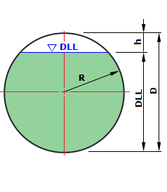
Vessel Volume & Level Calculation (2021년 11월 7일 수정) HTML 특수문자 리스트 (√ √ √ π Ø ø m²m³m⁴ ㄷ + - × ÷ ± ± ≤ ≥ ℃ ▶ ▽ △ ▲ ▼
Α Β Γ Δ Ε Ζ Η Θ Ι Κ Λ Μ Ν Ξ Ο Π Ρ Σ Τ Υ Φ Χ Ψ Ω α ε ο ο υ γ
α β γ δ ε ζ η θ ι κ λ μ ν ξ ο π ρ σ τ υ φ χ ψ ω ι ι ι υ ι γ
√ax2 + bx + c
출처 : http://kor.pe.kr/util/4/charmap2.htm
출처 : HTML에서 수식 표현하기
| A) For Spherical Tank | B) For Hemi-Spherical Head | C) For 2:1 Ellipsoidal Dish Head | D) For 10% Dish Head | ||||||||||||||||||||||||||||||||||||||||||||||||||||||||||||||||||||||||||||||||||||||||||||||||||||||||||||||||||||||||||||||||||||||||||||||||||||||||||||||||||||||||||||||||||||||||||||||||||||||||||||||||||||||||||||||||||||||||||||||||||||||||||||||||||||||||||||||||||||||||||||||||||||||||||||||||||||||||||||||||||||||||||||||||||||||||||||
|
|
|
| ||||||||||||||||||||||||||||||||||||||||||||||||||||||||||||||||||||||||||||||||||||||||||||||||||||||||||||||||||||||||||||||||||||||||||||||||||||||||||||||||||||||||||||||||||||||||||||||||||||||||||||||||||||||||||||||||||||||||||||||||||||||||||||||||||||||||||||||||||||||||||||||||||||||||||||||||||||||||||||||||||||||||||||||||||||||||||||
단, 수직 Vessel, FLAT BOTTOM 탱크, 구형탱크 제외
| 1) 저장탱크 의 설계사양 | 기호 | Value | Unit | |||
| 1 | B : 건축물의 폭 (m) / 저장탱크 의 외경(보냉포함) | B = | 27.000 | m | ||
| 2 | H : 건축물의 기준높이 (m) / 탱크 의 총높이 | H = | 32.700 | m | ||
| 4 | V0 : 기본 풍속 (m/s) - 울산지역 | Vo = | 38.0 | m/s | ||
| 5 | SC : 지표면 조도 구분 (KDS 41 12 00_표 5.5-1) | SC = | C | |||
| 6 | I : 중요도 분류 ((KDS 41 10 05, 표 5.5-6) | I = | 특 | |||
| 7 | A : 건축물의 유효 면적 | A = | 1027.9 | m2 | ||
| 8 | Cg : 용기의 무게 중심, Cg = 2/3 * H (m) | Cg = | 21.8 | m | ||
| 2) 풍하중 설계조건 [KDS 41 12 00] : | ||||||
| 2 | ρ : 공기 밀도 (1.225 kg/m2) (KDS 41 12 00_식(5.5-1)) | ρ = | 1.225 | kg/m3 | ||
| 3 | VH : 설계 풍속 (m/s), VH = Vo * KD * Kzr * Kzt * Iw | VH = | 45.524 | m/s | ||
| 1 | qH : 기준 높이 H 에 대한 설계속도압, qH = 0.5 * p * VH2 (N/m2) | qH = | 1269.37 | N/m2 | ||
| 4 | KD : 풍향계수 (KDS 41 12 00_5.5.3) | KD = | 1.0 | |||
| 5 | Kzr : 풍속고도분포계수로 기준높이 H 에서의 값 (KDS 41 12 00_표(5.5-2) | Kzr = | 1.198 | |||
| 6 | Kzt : 지형계수 (KDS 41 12 00_5.5.5) | Kzt = | 1.0 | |||
| 7 | Iw : 건축물의 중요도 계수 (KDS 41 12 00_표 5.5-5) | Iw = | 1.0 | |||
| 8 | z : 지표면에서의 임의 높이 (m) | z = | 32.7 | m | ||
| 9 | zb : 대기경계층 시작 높이 (m) (KDS 41 12 00_표 5.5-3) | zb = | 10.0 | m | ||
| 10 | Zg : 기준경도풍 높이 (m) (KDS 41 12 00_표 5.5-3) | Zg = | 350.0 | m | ||
| 11 | α : 풍속고도분포지수 (KDS 41 12 00_표 5.5-3) | α = | 0.15 | |||
| 12 | γD : 풍속변동계수 ((KDS 41 12 00_식 5.6-1.c) IH : 기준높이에서의 난류강도 식 5.5-3 a에서 z 를 H로 대체 IH = 0.1*(H/Zg)-α-0.05, IH = 0.1607 |  | γD = | 0.2579 | ||
| 13 | CD : 건축물의 풍력계수 (KDS 41 12 00_표 5.7-11) | CD = | 0.65 | |||
| 14 | BD : 비공진계수 ((KDS 41 12 00_ 식 5.6-1.d) | BD = | 0.6604 | |||
| 16 | LH : 기준높이에서의 난류스케일 (m) (KDS 41 12 00_식 5.6-1.e) | LH = | 104.4 | m | ||
[KDS 41 12 00] 건축물 설계하중.pdf (5. 풍하중)/ Wind Calculation
단, 수직 Vessel, FLAT BOTTOM 탱크, 구형탱크 제외
| No. | z(m) | Kzr | VH(m/s) | qH(N/m2) | WD(kN) | WD(Ton) | A(m2) |
| 1 | 32.700 | 1.198 | 45.524 | 1269.37 | 1559.082 | 15289.4 | 54.0 |
| 2 | 30.700 | 1.187 | 45.095 | 1245.55 | 1529.825 | 15002.5 | 54.0 |
| 3 | 28.700 | 1.175 | 44.639 | 1220.49 | 1499.046 | 14700.6 | 54.0 |
| 4 | 26.700 | 1.162 | 44.16 | 1194.44 | 1467.050 | 14386.8 | 54.0 |
| 5 | 24.700 | 1.149 | 43.647 | 1166.85 | 1433.163 | 14054.5 | 54.0 |
| 6 | 22.700 | 1.134 | 43.096 | 1137.57 | 1397.201 | 13701.9 | 54.0 |
| 7 | 20.700 | 1.118 | 42.503 | 1106.48 | 1359.015 | 13327.4 | 54.0 |
| 8 | 18.700 | 1.102 | 41.861 | 1073.31 | 1318.274 | 12927.9 | 54.0 |
| 9 | 16.700 | 1.083 | 41.158 | 1037.56 | 1274.365 | 12497.3 | 54.0 |
| 10 | 14.700 | 1.063 | 40.379 | 998.66 | 1226.587 | 12028.7 | 54.0 |
| 11 | 12.700 | 1.040 | 39.501 | 955.70 | 1173.822 | 11511.3 | 54.0 |
| 12 | 10.700 | 1.013 | 38.498 | 907.78 | 1114.965 | 10934.1 | 54.0 |
| 13 | 8.700 | 1.000 | 38.0 | 884.45 | 1086.310 | 10653.1 | 54.0 |
| 14 | 6.700 | 1.000 | 38.0 | 884.45 | 1086.310 | 10653.1 | 54.0 |
| 15 | 4.700 | 1.000 | 38.0 | 884.45 | 1086.310 | 10653.1 | 54.0 |
| 16 | 2.700 | 1.000 | 38.0 | 884.45 | 1086.310 | 10653.1 | 54.0 |
| 17 | 0.700 | 1.000 | 38.0 | 884.45 | 1086.310 | 10653.1 | 54.0 |
| 바닥 전단력, ΣWD = | 21783.945 | 213627.5 | 882.9 | ||||
|
|
| ||||||||||||||||||||||||||||||||||||||||||||||||||||||||||||||||||||||||||||||||||||||||||||||||||||||||||||||||||||||||||||||||||||||||||||||||||||||||||||||||||||||||||||||||||||||||||||||||||||||||||||||||||||||||||||||||||||||||||||||||||||||||||||||||||||||||||||||||||||||||||||||||||||||||||||||||||||||||||||||||||||||||||||||||||||||||||||||||||||||||||||||||||||||||||||||||||||||||||||||||||||||||||||||||||||||||||||||||||||||||||||||||||||||||||||||||||||||||||||||||||||||||||||||||||||||||||||||||||||||||||||||||||||||||||||||||||||||||||||||||||||||
SHELL BUCKLING CHECK [GL RULES]
출처 : ASME External Pressure, 링크 : Design https://www.pveng.com/home/asme-code-design/external-pressure-methods/
2 Designing for External Pressure
The easiest way to design for external pressure is to make the shell thick enough to make the vessel stable with an acceptable factor of
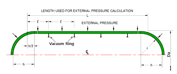
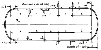
safety (pass code calculations). The length of the vessel used in the calculations includes some of the head at each end.
The calculations are found in ASME VIII-1 UG-28. The shell calculations are for a cylinder with supported ends
(the heads at each end). Calculations are also given for the heads which are treated as spheres.
Data Input :
출처 : Germanischer Lloyd (GL) RULE, External Pressure, 링크 : (크로아티아) BILOBE_실린더_계산_논문_620084.Senjanovic_Structure_design.pdf
출처 : Germanischer Lloyd (GL) RULE, External Pressure, 링크 : 003_STRUCTURE DESIGN OF CARGO TANKS IN RIVER LIQUEFIED GAS CARRIERS ds36_126.pdf
| Head Type | headType = | ||||||
| Design External Pressure | Pe = | 0.45 | bar | Full Vacuum F.V= 1.01325 bar | |||
| Outside diameter ( Cylinder ) | Da = | 4730 | mm | ||||
| (Assumed) Shell Plate Thickness | t = | 13.08 | mm | ||||
| Allowance for corrosion and wear | c = | 0 | mm | ||||
| Vacuum Ring pitch(ℓ), Or Length of shell(L) | ℓ = | 3722 | mm | ||||
| Modulus of elasticity at design temperature | Et = | 206000 | N/mm² | SA203-304(L), SA203-316(L) : 193,000 N/mm², Carbon and 9% Nickel : 206,000 N/mm², High Mn. : 175,000 N/mm² | |||
| Poisson's ratio | υ = | 0.3 | |||||
| integral number of waves; nw = 1.63 * [(Da/ℓ)2 * Da/tc]0.25 where, n > 2 and n > z | nw = | 8.01 | DNV-GL 7.1.3 91쪽 | ||||
| z = 3.141592 * Da / ( 2*ℓ ) | z = | 1.9962 | |||||
| Shell Thick. to Out-Diameter Ratio | (t-c) / Da = | 0.0027643 | |||||
| Safety factor against elastic buckling, Sk = 3 + [0.002 / (tc/R)] | Sk = | 3.3618 | |||||
| Vacuum Ring Size, Ex)H400x200x20x10 OR H400x20+300x10 | SIZE = | ex) T400x20+200x10 or FB100x6 | |||||
| SUBMIT | |||||||
3. ASME SEC. VIII Div. 1 설계외압에 의한 Vacuum Ring 시뮬레이션
[Alternate] Design External Pressure Check by ABS (ASME SEC.VIII Division 1 Rule )
| 1. Hemi-Spherical Head : | MATL = | SA553-Type.1 | ||||||||||||||||||||||||||||||||||||||||||||||||||||||||||||||||||||||||||||||||||||||||||||||||||||||||||||||||||||||||||||||||||||||
| Design External Pressure | Pe = | 0.045 | MPa | |||||||||||||||||||||||||||||||||||||||||||||||||||||||||||||||||||||||||||||||||||||||||||||||||||||||||||||||||||||||||||||||||||||
| Elastic modulus | Et = | 206000 | MPa | |||||||||||||||||||||||||||||||||||||||||||||||||||||||||||||||||||||||||||||||||||||||||||||||||||||||||||||||||||||||||||||||||||||
| Hemi-Spherical Head Long Radius, Ro = Do / 2 | Ro = | 2365.0 | mm | |||||||||||||||||||||||||||||||||||||||||||||||||||||||||||||||||||||||||||||||||||||||||||||||||||||||||||||||||||||||||||||||||||||
| Head Plate Thickness, | th = | 16.0 | mm | |||||||||||||||||||||||||||||||||||||||||||||||||||||||||||||||||||||||||||||||||||||||||||||||||||||||||||||||||||||||||||||||||||||
| Corrosion Allowance | CA = | 0.0 | mm | |||||||||||||||||||||||||||||||||||||||||||||||||||||||||||||||||||||||||||||||||||||||||||||||||||||||||||||||||||||||||||||||||||||
| Corroded Thickness | t = th-CA | 16.0 | mm | |||||||||||||||||||||||||||||||||||||||||||||||||||||||||||||||||||||||||||||||||||||||||||||||||||||||||||||||||||||||||||||||||||||
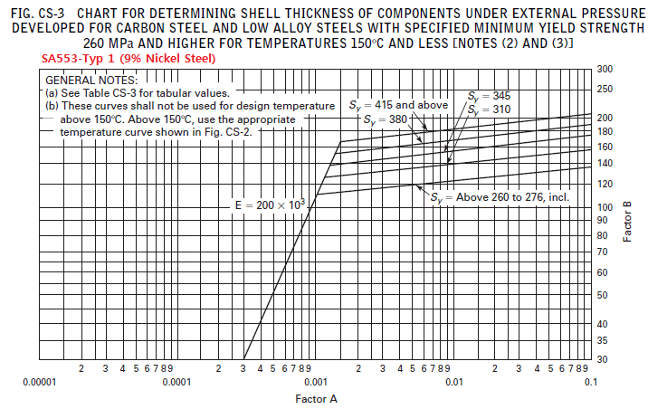
| Factor A for Head plate A = 0.125 / ( Ro / tc) | FACTOR A = | 0.0008457 | ||||||||||||||||||||||||||||||||||||||||||||||||||||||||||||||||||||||||||||||||||||||||||||||||||||||||||||||||||||||||||||||||||||||
| Factor B from ASME SEC. II Part D Fig. CS-3 Curve [Metric] | FACTOR B = | 84.56660 | MPa | |||||||||||||||||||||||||||||||||||||||||||||||||||||||||||||||||||||||||||||||||||||||||||||||||||||||||||||||||||||||||||||||||||||
| Pa = | 0.57212 572.12 | MPa kPa | |||||||||||||||||||||||||||||||||||||||||||||||||||||||||||||||||||||||||||||||||||||||||||||||||||||||||||||||||||||||||||||||||||||
| Buckling Check of Cylinder Shell Plate, | Pe(0.045) < Pa(0.57212) MPa | OK | ||||||||||||||||||||||||||||||||||||||||||||||||||||||||||||||||||||||||||||||||||||||||||||||||||||||||||||||||||||||||||||||||||||||
| 2. Shell plate : | MATL = | SA553-Type.1 | ||||||||||||||||||||||||||||||||||||||||||||||||||||||||||||||||||||||||||||||||||||||||||||||||||||||||||||||||||||||||||||||||||||||
| Design External Pressure, | Pe = | 0.045 | MPa | |||||||||||||||||||||||||||||||||||||||||||||||||||||||||||||||||||||||||||||||||||||||||||||||||||||||||||||||||||||||||||||||||||||
| Elastic modulus | Et = | 206000 | MPa | |||||||||||||||||||||||||||||||||||||||||||||||||||||||||||||||||||||||||||||||||||||||||||||||||||||||||||||||||||||||||||||||||||||
| Outside Diameter | Do = | 4730.0 | mm | |||||||||||||||||||||||||||||||||||||||||||||||||||||||||||||||||||||||||||||||||||||||||||||||||||||||||||||||||||||||||||||||||||||
| Stiffener pitch | L = | 3722.0 | mm | |||||||||||||||||||||||||||||||||||||||||||||||||||||||||||||||||||||||||||||||||||||||||||||||||||||||||||||||||||||||||||||||||||||
| Recommend Stiffener pitch (추천 Picth by Bob-LONG for API 620 Tank) | Ls = | 11409.1 | mm | |||||||||||||||||||||||||||||||||||||||||||||||||||||||||||||||||||||||||||||||||||||||||||||||||||||||||||||||||||||||||||||||||||||
| (Assumed) Shell Plate Thickness | ts = | 13.075 | mm | |||||||||||||||||||||||||||||||||||||||||||||||||||||||||||||||||||||||||||||||||||||||||||||||||||||||||||||||||||||||||||||||||||||
| Corrosion Allowance | CA = | 0.0 | mm | |||||||||||||||||||||||||||||||||||||||||||||||||||||||||||||||||||||||||||||||||||||||||||||||||||||||||||||||||||||||||||||||||||||
| Corroded Thickness | t = ts-CA | 13.075 | mm | |||||||||||||||||||||||||||||||||||||||||||||||||||||||||||||||||||||||||||||||||||||||||||||||||||||||||||||||||||||||||||||||||||||
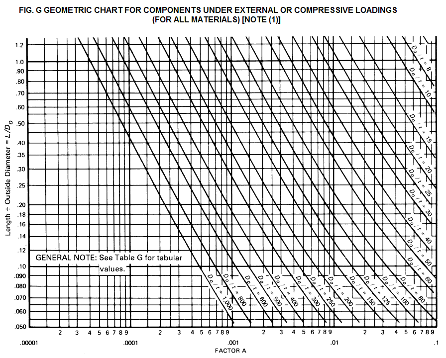
| Stiffener pitch to Diameter Ratio, L/Do > 0.055, OK! [Step 1 from FIG. G] | L / Do = | 0.7869 | Ref. FIG. G | |||||||||||||||||||||||||||||||||||||||||||||||||||||||||||||||||||||||||||||||||||||||||||||||||||||||||||||||||||||||||||||||||||||
| Out-Diameter to thickness ratio, Do/tc < 1000, OK! [Step 2 from FIG. G] | Do / t = | 361.7591 | Ref. FIG. G | |||||||||||||||||||||||||||||||||||||||||||||||||||||||||||||||||||||||||||||||||||||||||||||||||||||||||||||||||||||||||||||||||||||
| Factor A for Cylinderical Shells form ASME SEC II, Part D, FIG-G. | FACTOR A = | 0.0002550 | Ref. FIG. G | |||||||||||||||||||||||||||||||||||||||||||||||||||||||||||||||||||||||||||||||||||||||||||||||||||||||||||||||||||||||||||||||||||||
| Factor B from ASME SEC. II Part D Fig. CS-3 Curve [Metric] | FACTOR B = | 25.49597 | MPa | |||||||||||||||||||||||||||||||||||||||||||||||||||||||||||||||||||||||||||||||||||||||||||||||||||||||||||||||||||||||||||||||||||||
| Pa = | 0.09397 93.97 | MPa kPa | |||||||||||||||||||||||||||||||||||||||||||||||||||||||||||||||||||||||||||||||||||||||||||||||||||||||||||||||||||||||||||||||||||||
| Buckling Check of Cylinder Shell Plate, ASME VIII, Div 1 | Pe(0.045) < Pa(0.09397) MPa Pe(0.45) < Pa(0.9397) bar.g | OK | ||||||||||||||||||||||||||||||||||||||||||||||||||||||||||||||||||||||||||||||||||||||||||||||||||||||||||||||||||||||||||||||||||||||
| [미국 수소법 CGA_H3] Pc = [2.6×Et×(tc/Da)2.5] / [(L/Da) - 0.45×(tc/Da)0.5] | Pc = | 0.2819 | MPa | |||||||||||||||||||||||||||||||||||||||||||||||||||||||||||||||||||||||||||||||||||||||||||||||||||||||||||||||||||||||||||||||||||||
| [minL 역계산] minL = [(2.6×Et×(tc/Da)2.5) / Pc + 0.45×(tc/Da)0.5] × D | minL = | 3722 | mm | |||||||||||||||||||||||||||||||||||||||||||||||||||||||||||||||||||||||||||||||||||||||||||||||||||||||||||||||||||||||||||||||||||||
| Buckling Check of Cylinder Shell Plate, by CGA H-3 Rules Pe = Safety Factor 2 ⋅ F/V = 2.0265 bar.g | Pe(0.2027) < Pc(0.2819) MPa Pe(2.027) < Pc(2.819) bar.g | OK | ||||||||||||||||||||||||||||||||||||||||||||||||||||||||||||||||||||||||||||||||||||||||||||||||||||||||||||||||||||||||||||||||||||||
| 3. Stiffener Ring ( Vacuum Ring ) : | MATL = | SA553-Type.1 | ||||||||||||||||||||||||||||||||||||||||||||||||||||||||||||||||||||||||||||||||||||||||||||||||||||||||||||||||||||||||||||||||||||||
| Stiffener Ring Size | Size = | T400x20+200x10 | ||||||||||||||||||||||||||||||||||||||||||||||||||||||||||||||||||||||||||||||||||||||||||||||||||||||||||||||||||||||||||||||||||||||
| Section Area of Stiffener Ring | As = | 98 | cm² | |||||||||||||||||||||||||||||||||||||||||||||||||||||||||||||||||||||||||||||||||||||||||||||||||||||||||||||||||||||||||||||||||||||
| [UG-29 Step 1.] B = 3/4 ⋅ Pe ⋅ Do / (t+As/Ls) | B = | 10.1628 | MPa | |||||||||||||||||||||||||||||||||||||||||||||||||||||||||||||||||||||||||||||||||||||||||||||||||||||||||||||||||||||||||||||||||||||
| [UG-29 Step 5.] A = 2 ⋅ B / Et | A = | 0.0000987 | ||||||||||||||||||||||||||||||||||||||||||||||||||||||||||||||||||||||||||||||||||||||||||||||||||||||||||||||||||||||||||||||||||||||
| [UG-29(a)] Required moment of inertia of the combined ring-shell cross section Is' = Do² ⋅ Ls(t+As/Ls) ⋅ A / 10.9 ⋅ [mm4] Is' = 4730² ⋅ 3722 ⋅ (13.075+9800/3722) ⋅ 0.0000987 / 10.9 [mm4] | Is' = | 1184.05 | cm⁴ | |||||||||||||||||||||||||||||||||||||||||||||||||||||||||||||||||||||||||||||||||||||||||||||||||||||||||||||||||||||||||||||||||||||
| [UG-29(a)] available moment of inertia of combined ring-shell cross section See. Bellow Table | I' = | 34554.58 | cm⁴ | |||||||||||||||||||||||||||||||||||||||||||||||||||||||||||||||||||||||||||||||||||||||||||||||||||||||||||||||||||||||||||||||||||||
| Check of inertia cross section, Is' / I' < 1.0 OK | Is' / I' = | 0.0343 < 1.0 OK | ||||||||||||||||||||||||||||||||||||||||||||||||||||||||||||||||||||||||||||||||||||||||||||||||||||||||||||||||||||||||||||||||||||||
Available moment of inertia calculation (I') : Stiffener Size : T400x20+200x10
| ||||||||||||||||||||||||||||||||||||||||||||||||||||||||||||||||||||||||||||||||||||||||||||||||||||||||||||||||||||||||||||||||||||||||
 | ||||||||||||||||||||||||||||||||||||||||||||||||||||||||||||||||||||||||||||||||||||||||||||||||||||||||||||||||||||||||||||||||||||||||
 | ||||||||||||||||||||||||||||||||||||||||||||||||||||||||||||||||||||||||||||||||||||||||||||||||||||||||||||||||||||||||||||||||||||||||
4. ASME SEC. VIII Div. 2 설계외압에 의한 Vacuum Ring 시뮬레이션
[Alternate] Design External Pressure Check by ABS (ASME SEC.VIII Division 2 Rule )
A. Spherical Shell or Hemi-Head Required Thickness: Div.2 EQ.4.4.2, EQ.4.4.7
| 1. Spherical Shell or Hemi-Spherical Head : | MATL = | SA553-Type.1 | |
| Design External Pressure, | Pe = | 0.045 | MPa |
| Elastic modulus | Et = | 206000 | MPa |
| Minimum Specified Yield Strength at Design Temperature(80℃) | Sy = | 400.0 | MPa |
| Hemi-Spherical Head Long Radius, Ro = Do / 2 | Ro = | 2365.0 | mm |
| Head Plate Nominal Thickness, | th = | 16.0 | mm |
| Head Plate Corrosion Allowance | CA = | 0.0 | mm |
| Head Plate Corroded Thickness | t = th-CA | 16.0 | mm |
| Predicted Elastic buckling stress, Fhe = 0.075 × Ey × [tc / Ro] (Eqn. 4.4.53) | Fhe = | 104.52 | MPa |
| Safety Factor If Fic ≤ 0.55×Sy then FS = 2.0 Eqn. 4.4.1) | FS = | 2.000 | |
| If Fhe ≤ 0.55×Sy then Fha = Fhe / FS (Eqn. 4.4.57) | Fha = | 52.26 | MPa |
| Allowable External Pressure, Pa = FS × Fha × [t / Ro] (Eqn. 4.4.58) | Pa = | 0.70714 | MPa |
| Req'd Min. Head plate thickness for Ext. Pressure Tmin_EP = Ro × Pe / (FS × Fha) + CA | Tmin_EP = | 1.02 | mm |
| Check : Pe ≤ Pa OK, Tmin_EP ≤ t | Pe ≤ Pa | O.K |
| No. | t mm | Do mm | Fhe MPa | Mx | Ch | Fic MPa | Ae | FS | Fha MPa | Pe Mpa | < Pa OK MPa |
| 1 | 10.0 | 4730 | 39.8156 | 15.4684 | 0.0618 | 39.81564 | 0.00019328 | 2.0000 | 19.9078 | 0.045 | < 0.0779 OK |
Mx=[15.4684], Ch=[0.0618], Fhe=[39.8156], Fic=[39.8156], FS=[2.0]
Pe(0.045 MPa) < Pa_div2=[0.0779] Mpa , Pa_div2=[0.779] bar.g, OK
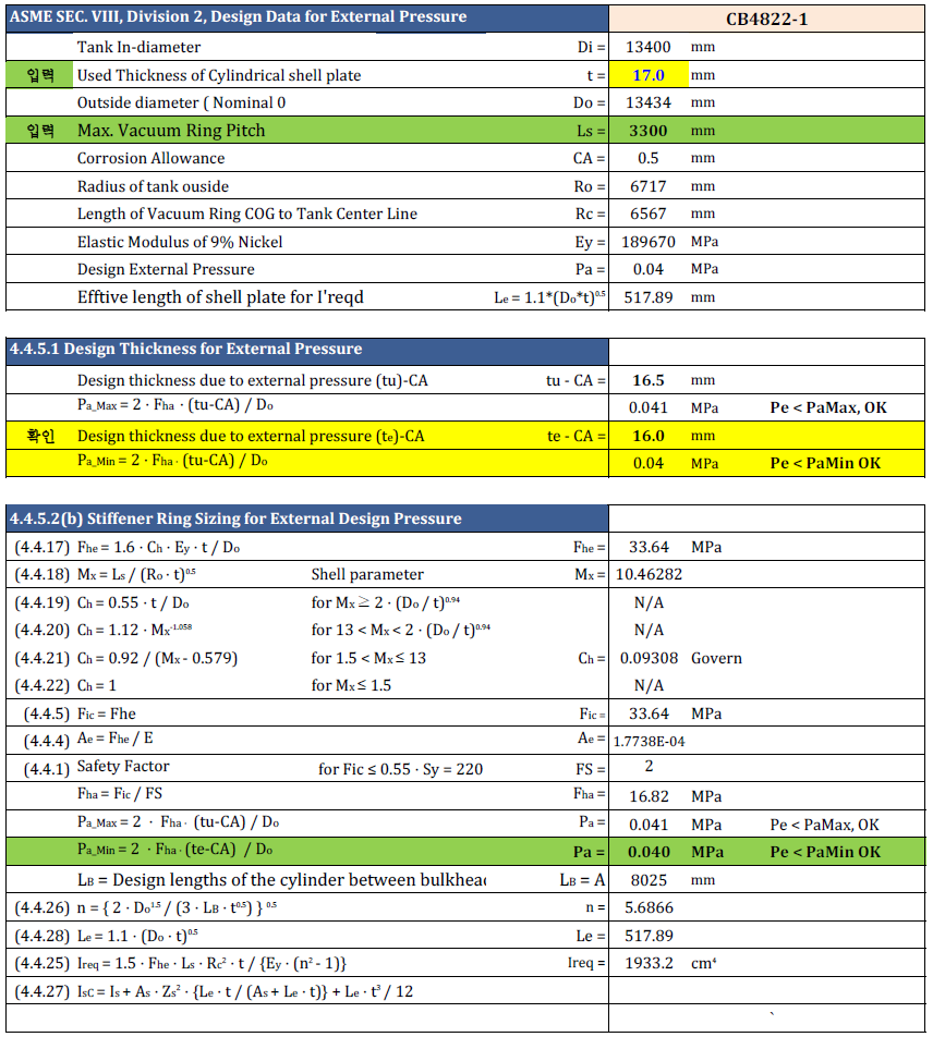
ASME SEC. VIII Div. 2 Examples : [파일 : (SB-Q21-0618_0628) 선보공업_2nd_견적_강도계산.xlsx]
1. Check by DNV-GL RULES, (설계외압에 의한 Vacuum Ring 시뮬레이션) 아래 Formula 변천사 출처
Case A ) 중요 : Safety Fctor Sk = 4, Max( 4, 3 + [ 0.002 / (t-c / R) ] )
| n | GL Rules Pcr_GL (bar.g) Sk = 3.3618 | DNV-GL RULES Pcr_DNV (bar.g) when, Sk = 4.0 | Remark |
| 4 | 9.1795 | 7.7148 | 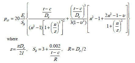 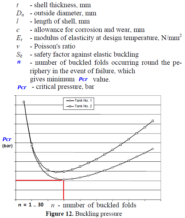 |
| 5 | 2.9590 | 2.4869 | |
| 6 | 1.3600 | 1.1430 | |
| 7 | 0.9233 | 0.7760 | |
| 8 | 0.8525 (Sk = 3.3618) | 0.7165 ( Sk = 4.0 ) Minimum Pcr( critical pressure ) bar.g | |
| 9 | 0.9231 | 0.7758 | |
| 10 | 1.0612 | 0.8919 | |
| 11 | 1.2393 | 1.0416 | |
| 12 | 1.4463 | 1.2156 | |
| 13 | 1.6773 | 1.4096 | |
| 14 | 1.9297 | 1.6218 | |
| 15 | 2.2026 | 1.8512 | |
| 16 | 2.4953 | 2.0972 | |
| 17 | 2.8074 | 2.3595 | |
| 18 | 3.1388 | 2.6380 | |
| 19 | 3.4893 | 2.9326 | |
| 20 | 3.8589 | 3.2432 | |
| 21 | 4.2476 | 3.5698 | |
| 22 | 4.6552 | 3.9124 | |
| 23 | 5.0819 | 4.2710 | |
| 24 | 5.5275 | 4.6455 | |
| 25 | 5.9921 | 5.0360 | |
| 26 | 6.4757 | 5.4425 | |
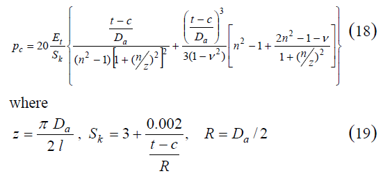
| Where, Shell plate Material : SA553-Type.1 Vacuum Ring Pitch, L = [3722.0] mm, Buckling Coefficient, z = 3.141592 * Da / ( 2 * L ) = 1.9962 The critical pressure is found by an iteration process over the range n, where n > z. Buckling Safety factor, Sk = 3 + (0.002/(tc/Ro)) = 3.36176 n = 8 - number of buckled folds occurring round the periphery in the event of failure, which give minimum pcr value. Pcr = 0.8525 bar.g, Minimum Pcr value. | |||
| Evaluation : (평가결과) 1. Design External Pressure : 0.45(bar) < Cretical External Pressure 0.8525(bar) 이므로 [안전]합니다. 2. 안전율 [Pe/Pcr = 0.5278] 로써 OVER DESIGN 상태이므로 Shell 두께를 적정두께로 줄이시기를 추천 합니다. | |||
2. Check by DNV-GL vs. ABS Rules (ASME SEC. VIII Div.1 설계외압에 의한 Vacuum Ring 시뮬레이션
Case B ) 중요 : Safety Fctor Sk = 3 + [0.002 / (t-c / R) ]
| DNV-GL when, Sk = 3 + [0.002 / (t-c / R) | ABS Rules = ASME SEC. VIII Division 1 Do/t = 361.76 < 1000 이하 OK, L/Do = 0.78689, CA = 0 mm | ||||||||
| t(mm) | Sk | nz | Pcr (bar) | t(mm) | Do / tc | Factor A | Factor B | Pa (bar) | Pcr/Pa |
| 10 | 3.473 | 18.428 | 0.41993 | 10 | 473.000 | 0.00016676 | 16.676 | 0.4701 | 0.8933 |
| 10.5 | 3.45048 | 17.984 | 0.47797 | 10.5 | 450.476 | 0.00018029 | 18.029 | 0.5336 | 0.8957 |
| Where, Shell Material : SA553-Type.1, Vacuum Ring Pitch L = [3722.0] mm, n = 18 , number of buckled folds occurring round the periphery in the event of failure, which give minimum pcr value. Pcr = 0.8525 bar.g, Minimum Pcr value. | |||||||||
| Evaluation : (평가결과) 1. Shell 두께 10.5 (mm) 일 경우, Design External Pressure : 0.45(bar) < Cretical External Pressure 0.4780(bar) 이므로 [안전]합니다. 2. 안전율 [Pe/Pcr = 0.9415] 로써 OVER DESIGN 상태이므로 Shell 두께를 적정두께로 줄이시기를 추천 합니다. | |||||||||
필요한 단면 2차 모멘트 ( DNV-GL Rules)
DNVGL-RU-SHIP-Pt5Ch7 (2017) Liquefied gas tankers.pdf Pt5. Ch.7 Secction 22
2.4.1 2.4 Scantling due to external pressure
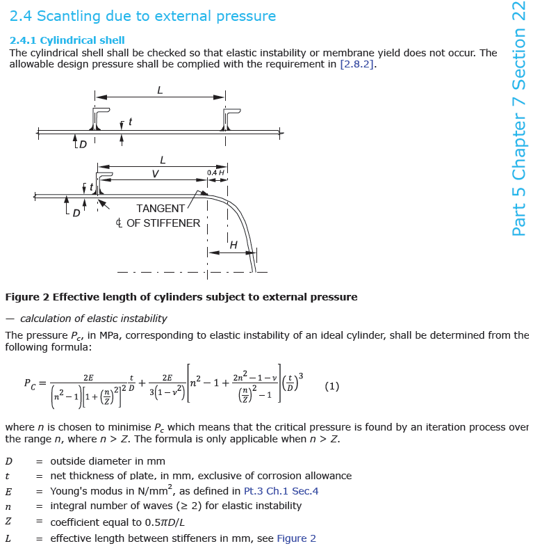
2.4.4 Stiffening rings
The requirements for scantling of stiffening rings are given in terms of minimum moment of inertia for the member, in mm⁴.

Ix = 0.18 * 4730 * 0.045 * 3722 * 4730²/ 206000 = 1.5487367E7 mm⁴= 1548.74 cm⁴
Where :
Ds = diameter to the neutral axis of stiffener in mm
Ped = external design pressure in MPa defined in [1.2.4].
Ls = 0.75 * SQRT(D*t)
The length of the shell in mm contributing to the moment of inertia is limited by
Stiffening rings shall extent completely around the circumference of the shell.
2.4.2) Hemi-Spherical Head for Allowable Compressive Stress
출처 : 002_IMO C형 독립탱크의 설계치수 계산과정 및 평가방법에 대한 고찰 7 쪽 Consideration for IMO Type C Independent Tank Rule Scantling Process and Evaluation Methods-1.pdf
The spherical shell shall be checked so that elastic instability or membrane yield does not occur.
The allowable design pressure shall be complied with the requirement in [2.8.2].
calculation of elastic instability
The pressure Pc, in bar.g, corresponding to elastic instability of a head plate,
shall be determined from the following formula:
Pc = 2.4 * E * [ (tHead-CA) /R ]² = 2.4 * 206000.0 * [(16.0 - 0.75) / 2365]² = 20.557 bar.g
Py = 20 * Fy * [(tHead-CA) / R ] = 20 * 400.0 * (16.0 - 0.75) / 2365) = 51.586 bar.g
Acceptance criteria for Head Plate :
Pe(0.45) < Min(Pc / 3, Py/3 ) then OK
Pe(0.45) < Min( 20.557/3, 51.586/3 ) then OK
Pe(0.45) < Min( 6.852, 17.195 ) then OK
출처 : (크로아티아) BILOBE_실린더_계산_논문_620084.Senjanovic_Structure_design.pdf
8. SHELL BUCKLING ANALYSIS
8.1. CYLINDRICAL SHELL
In the case of a large external pressure a segment of
the cylindrical tank shell between the two vacuum rings
may lose stability. According to the GL Rules the critical
pressure for elastic buckling of a cylindrical shell is determined
by the following formula [5]
출처 : 003_STRUCTURE DESIGN OF CARGO TANKS IN RIVER LIQUEFIED GAS CARRIERS ds36_126.pdf
4. Shell Buckling
4.1 Cylindrical shell
In the case of external pressure a segment of the cylindrical tank shell between the two vacuum rings
may lose stability. According to the GL Rules the critical pressure for elastic buckling of a cylindrical
shell is determined by the following formula [Rules GL 2000]:

출처 DNV_GL : DNVGL-RU-SHIP-Pt4Ch7.pdf 91 쪽
Stiffener Size : T400x20+200x10 Shell Section : t9 x 230 mm
| No. | b | d | A=b*d | y | A*y | h = y-C1 | Ah² | Ig=b*d³/12 | SKETCH |
| cm | cm | cm² | cm | cm³ | (cm) | cm⁴ | cm⁴ | 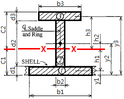 | |
| 3 | 20.0 | 1.0 | 20.0 | 40.425 | 808.5 | 20.21 | 8167.27 | 1.67 | |
| 2 | 2.0 | 39.0 | 78.0 | 20.425 | 1593.15 | 0.21 | 3.37 | 9886.5 | |
| Shell | 23.01 | 0.925 | 21.28 | 0.4625 | 9.84 | -19.75 | 8304.31 | 1.52 | |
| SUM | ∑ = | 119.28 | 2411.49 | 16474.95 | 9889.68 |
| C1 | = ∑(AY) / ∑(A) (무게중심 위치) | C1 = | 20.217 | cm | 무게중심에서 FLANGE 하단 까지 떨어진 거리 |
| C2 | = H - C1 | C2 = | 20.708 | cm | 무게중심에서 FLANGE 상단 까지 떨어진 거리 |
| ∑(A) | = Sum of Section Area (단면적) | ∑(A)= | 119.28 | cm² | 단면적 (빗금전체) |
| Ix | = ∑(Ah²) + ∑(Ig) | Ix = | 26364.64 | cm⁴ | X축 단면2차모멘트 (Moment of inertia) |
| Zx | = Ix / Max(C1, C2) | Zx = | 1273.16 | cm³ | X축 단면계수 (Section Modulus) |
| Zmax | = Ix / Min(C1, C2) | Zmax = | 1304.08 | cm³ | X축 (최대) 단면계수 |
| Rx | = SQRT( Ix / A ) | Rx = | 14.87 | cm | X축 회전반경 |
| Ry | = SQRT( Iy / A ) | Ry = | 3.7 | cm | Y축 회전반경 |
| Section Area(Shell 포함) | Sarea = | 119.28 | cm² | Section Area(Shell 포함) | |
| Ring 단면적 (Shell 제외) | ARing = | 98 | cm² | Ring 단면적 (Shell 제외) | |
| Ring 원주길이 | Leng = | 6.22 | m | Ring 길이(m) = 3.141592×(Di-C1) | |
| Ring 단위중량 (kg/m), | WTm = | 76.93 | kg/m | 단위중량(kg/m) | |
| Ring Weight, Shell(1) 제외 중량 | WT = | 478.5 | kg | Ring 1 PCS 중량(kg) | |
Stiffener Size : FB 300x10 Shell Section : t10 x 200 mm
| No. | b | d | A=b*d | y | A*y | h = y-C1 | Ah² | Ig=b*d³/12 | SKETCH |
| cm | cm | cm² | cm | cm³ | (cm) | cm⁴ | cm⁴ | 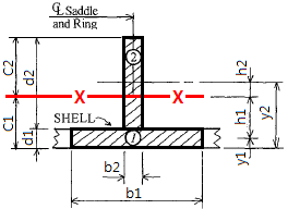 | |
| 2 | 1.0 | 30.0 | 30.0 | 16.0 | 480 | 6.2 | 1153.2 | 2250 | |
| 1 | 20.0 | 1.0 | 20.0 | 0.5 | 10 | -9.3 | 1729.8 | 1.67 | |
| SUM | ∑ = | 50 | 490 | 2883 | 2251.67 |
| C1 | = ∑(AY) / ∑(A) (무게중심 위치) | C1 = | 9.8 | cm | 무게중심에서 FLANGE 하단 까지 떨어진 거리 |
| C2 | = H - C1 | C2 = | 21.2 | cm | 무게중심에서 FLANGE 상단 까지 떨어진 거리 |
| ∑(A) | = Sum of Section Area (단면적) | ∑(A)= | 50.00 | cm² | 단면적 (빗금전체) |
| Ix | = ∑(Ah²) + ∑(Ig) | Ix = | 5134.67 | cm⁴ | X축 단면2차모멘트 (Moment of inertia) |
| Zx | = Ix / Max(C1, C2) | Zx = | 242.2 | cm³ | X축 단면계수 (Section Modulus) |
| Zmax | = Ix / Min(C1, C2) | Zmax = | 523.95 | cm³ | X축 (최대) 단면계수 |
| Rx | = SQRT( Ix / A ) | Rx = | 10.13 | cm | X축 회전반경 |
| Ry | = SQRT( Iy / A ) | Ry = | 3.66 | cm | Y축 회전반경 |
| Section Area(Shell 포함) | Sarea = | 50 | cm² | Section Area(Shell 포함) | |
| Ring 단면적 (Shell 제외) | ARing = | 30 | cm² | Ring 단면적 (Shell 제외) | |
| Ring 원주길이 | Leng = | 6.25 | m | Ring 길이(m) = 3.141592×(Di-C1) | |
| Ring 단위중량 (kg/m), | WTm = | 23.55 | kg/m | 단위중량(kg/m) | |
| Ring Weight, Shell(1) 제외 중량 | WT = | 147.2 | kg | Ring 1 PCS 중량(kg) | |
Stiffener Size : T 400x20+150x10 Shell Section : t15 x 200 mm
| No. | b | d | A=b*d | y | A*y | h = y-C1 | Ah² | Ig=b*d³/12 | SKETCH |
| cm | cm | cm² | cm | cm³ | (cm) | cm⁴ | cm⁴ |  | |
| 3 | 15.0 | 1.0 | 15.0 | 41.0 | 615 | 22.5 | 7593.75 | 1.25 | |
| 2 | 2.0 | 39.0 | 78.0 | 21.0 | 1638 | 2.5 | 487.5 | 9886.5 | |
| Shell | 20.0 | 1.5 | 30.0 | 0.75 | 22.5 | -17.75 | 9451.88 | 5.63 | |
| SUM | ∑ = | 123 | 2275.5 | 17533.13 | 9893.38 |
| C1 | = ∑(AY) / ∑(A) (무게중심 위치) | C1 = | 18.5 | cm | 무게중심에서 FLANGE 하단 까지 떨어진 거리 |
| C2 | = H - C1 | C2 = | 23.0 | cm | 무게중심에서 FLANGE 상단 까지 떨어진 거리 |
| ∑(A) | = Sum of Section Area (단면적) | ∑(A)= | 123.00 | cm² | 단면적 (빗금전체) |
| Ix | = ∑(Ah²) + ∑(Ig) | Ix = | 27426.5 | cm⁴ | X축 단면2차모멘트 (Moment of inertia) |
| Zx | = Ix / Max(C1, C2) | Zx = | 1192.46 | cm³ | X축 단면계수 (Section Modulus) |
| Zmax | = Ix / Min(C1, C2) | Zmax = | 1482.51 | cm³ | X축 (최대) 단면계수 |
| Rx | = SQRT( Ix / A ) | Rx = | 14.93 | cm | X축 회전반경 |
| Ry | = SQRT( Iy / A ) | Ry = | 3.26 | cm | Y축 회전반경 |
| Section Area(Shell 포함) | Sarea = | 123 | cm² | Section Area(Shell 포함) | |
| Ring 단면적 (Shell 제외) | ARing = | 93 | cm² | Ring 단면적 (Shell 제외) | |
| Ring 원주길이 | Leng = | 6.23 | m | Ring 길이(m) = 3.141592×(Di-C1) | |
| Ring 단위중량 (kg/m), | WTm = | 73.01 | kg/m | 단위중량(kg/m) | |
| Ring Weight, Shell(1) 제외 중량 | WT = | 454.5 | kg | Ring 1 PCS 중량(kg) | |
Stiffener Size : H 200 * 20 + 100 x 10 Shell Section : t20 x 150 mm
| No. | b | d | A=b*d | y | A*y | h = y-C1 | Ah² | Ig=b*d³/12 | SKETCH |
| cm | cm | cm² | cm | cm³ | (cm) | cm⁴ | cm⁴ | 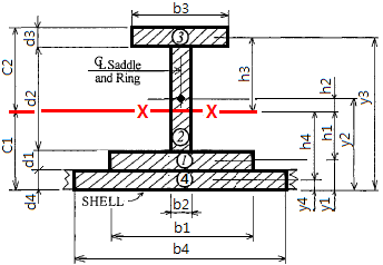 | |
| 3 | 10.0 | 2.0 | 20.0 | 22.0 | 440 | 13.47 | 3626.66 | 6.67 | |
| 2 | 1.0 | 17.0 | 17.0 | 12.5 | 212.5 | 3.97 | 267.4 | 409.42 | |
| 1 | 10.0 | 2.0 | 20.0 | 3.0 | 60 | -5.53 | 612.5 | 6.67 | |
| Shell | 15.0 | 2.0 | 30.0 | 1.0 | 30 | -7.53 | 1702.83 | 10 | |
| SUM | ∑ = | 87 | 742.5 | 6209.4 | 432.75 |
| C1 | = ∑(AY) / ∑(A) (무게중심 위치) | C1 = | 8.534 | cm | 무게중심에서 FLANGE 하단 까지 떨어진 거리 |
| C2 | = H - C1 | C2 = | 14.466 | cm | 무게중심에서 FLANGE 상단 까지 떨어진 거리 |
| ∑(A) | = Sum of Section Area (단면적) | ∑(A)= | 87.00 | cm² | 단면적 (빗금전체) |
| Ix | = ∑(Ah²) + ∑(Ig) | Ix = | 6642.15 | cm⁴ | X축 단면2차모멘트 (Moment of inertia) |
| Zx | = Ix / Max(C1, C2) | Zx = | 459.16 | cm³ | X축 단면계수 (Section Modulus) |
| Zmax | = Ix / Min(C1, C2) | Zmax = | 778.32 | cm³ | X축 (최대) 단면계수 |
| Rx | = SQRT( Ix / A ) | Rx = | 8.74 | cm | X축 회전반경 |
| Ry | = SQRT( Iy / A ) | Ry = | 3.21 | cm | Y축 회전반경 |
| Section Area(Shell 포함) | Sarea = | 87 | cm² | Section Area(Shell 포함) | |
| Ring 단면적 (Shell 제외) | ARing = | 57 | cm² | Ring 단면적 (Shell 제외) | |
| Ring 원주길이 | Leng = | 6.26 | m | Ring 길이(m) = 3.141592×(Di-C1) | |
| Ring 단위중량 (kg/m), | WTm = | 44.75 | kg/m | 단위중량(kg/m) | |
| Ring Weight, Shell(1) 제외 중량 | WT = | 279.9 | kg | Ring 1 PCS 중량(kg) | |
Stiffener Size : HB 400x200x20/10 Shell Section : t25 x 300 mm
| No. | b | d | A=b*d | y | A*y | h = y-C1 | Ah² | Ig=b*d³/12 | SKETCH |
| cm | cm | cm² | cm | cm³ | (cm) | cm⁴ | cm⁴ |  | |
| 3 | 20.0 | 2.0 | 40.0 | 42.5 | 1700 | 28 | 31351.04 | 13.33 | |
| 2 | 1.0 | 37.0 | 37.0 | 23.0 | 851 | 8.5 | 2670.73 | 4221.08 | |
| 1 | 20.0 | 2.0 | 40.0 | 3.5 | 140 | -11 | 4843.52 | 13.33 | |
| Shell | 30.0 | 2.5 | 75.0 | 1.25 | 93.75 | -13.25 | 13175.14 | 39.06 | |
| SUM | ∑ = | 192 | 2784.75 | 52040.43 | 4286.81 |
| C1 | = ∑(AY) / ∑(A) (무게중심 위치) | C1 = | 14.504 | cm | 무게중심에서 FLANGE 하단 까지 떨어진 거리 |
| C2 | = H - C1 | C2 = | 28.996 | cm | 무게중심에서 FLANGE 상단 까지 떨어진 거리 |
| ∑(A) | = Sum of Section Area (단면적) | ∑(A)= | 192.00 | cm² | 단면적 (빗금전체) |
| Ix | = ∑(Ah²) + ∑(Ig) | Ix = | 56327.25 | cm⁴ | X축 단면2차모멘트 (Moment of inertia) |
| Zx | = Ix / Max(C1, C2) | Zx = | 1942.59 | cm³ | X축 단면계수 (Section Modulus) |
| Zmax | = Ix / Min(C1, C2) | Zmax = | 3883.57 | cm³ | X축 (최대) 단면계수 |
| Rx | = SQRT( Ix / A ) | Rx = | 17.13 | cm | X축 회전반경 |
| Ry | = SQRT( Iy / A ) | Ry = | 6.57 | cm | Y축 회전반경 |
| Section Area(Shell 포함) | Sarea = | 192 | cm² | Section Area(Shell 포함) | |
| Ring 단면적 (Shell 제외) | ARing = | 117 | cm² | Ring 단면적 (Shell 제외) | |
| Ring 원주길이 | Leng = | 6.24 | m | Ring 길이(m) = 3.141592×(Di-C1) | |
| Ring 단위중량 (kg/m), | WTm = | 91.85 | kg/m | 단위중량(kg/m) | |
| Ring Weight, Shell(1) 제외 중량 | WT = | 572.9 | kg | Ring 1 PCS 중량(kg) | |
Stiffener Size : H 500x200x20/10 Shell Section : t30 x 400 mm
| No. | b | d | A=b*d | y | A*y | h = y-C1 | Ah² | Ig=b*d³/12 | SKETCH |
| cm | cm | cm² | cm | cm³ | (cm) | cm⁴ | cm⁴ |  | |
| 3 | 20.0 | 2.0 | 40.0 | 53.0 | 2120 | 37.62 | 56601.55 | 13.33 | |
| 2 | 1.0 | 47.0 | 47.0 | 28.5 | 1339.5 | 13.12 | 8086.62 | 8651.92 | |
| 1 | 20.0 | 2.0 | 40.0 | 4.0 | 160 | -11.38 | 5182.91 | 13.33 | |
| Shell | 40.0 | 3.0 | 120.0 | 1.5 | 180 | -13.88 | 23128.52 | 90 | |
| SUM | ∑ = | 247 | 3799.5 | 92999.6 | 8768.58 |
| C1 | = ∑(AY) / ∑(A) (무게중심 위치) | C1 = | 15.383 | cm | 무게중심에서 FLANGE 하단 까지 떨어진 거리 |
| C2 | = H - C1 | C2 = | 38.617 | cm | 무게중심에서 FLANGE 상단 까지 떨어진 거리 |
| ∑(A) | = Sum of Section Area (단면적) | ∑(A)= | 247.00 | cm² | 단면적 (빗금전체) |
| Ix | = ∑(Ah²) + ∑(Ig) | Ix = | 101,768 | cm⁴ | X축 단면2차모멘트 (Moment of inertia) |
| Zx | = Ix / Max(C1, C2) | Zx = | 2635.32 | cm³ | X축 단면계수 (Section Modulus) |
| Zmax | = Ix / Min(C1, C2) | Zmax = | 6615.63 | cm³ | X축 (최대) 단면계수 |
| Rx | = SQRT( Ix / A ) | Rx = | 20.3 | cm | X축 회전반경 |
| Ry | = SQRT( Iy / A ) | Ry = | 8.69 | cm | Y축 회전반경 |
| Section Area(Shell 포함) | Sarea = | 247 | cm² | Section Area(Shell 포함) | |
| Ring 단면적 (Shell 제외) | ARing = | 127 | cm² | Ring 단면적 (Shell 제외) | |
| Ring 원주길이 | Leng = | 6.23 | m | Ring 길이(m) = 3.141592×(Di-C1) | |
| Ring 단위중량 (kg/m), | WTm = | 99.7 | kg/m | 단위중량(kg/m) | |
| Ring Weight, Shell(1) 제외 중량 | WT = | 621.6 | kg | Ring 1 PCS 중량(kg) | |
double GET_I( 0.5, 9.86, 0.5, 6.0, 0.5, 4.0, 0,0 ) = [28.8025] cm⁴
| No. | b | d | A=b*d | y | A*y | h = y-C1 | Ah² | Ig=b*d³/12 | SKETCH |
| mm | mm | mm² | mm | mm³ | (mm) | mm⁴ | mm⁴ |  | |
| 2 | 0.5 | 6.0 | 3.0 | 3.5 | 10.5 | 2.02 | 12.241 | 9 | |
| 1 | 9.86 | 0.5 | 4.93 | 0.25 | 1.233 | -1.23 | 7.459 | 0.103 | |
| SUM | ∑ = | 7.93 | 11.733 | 19.7 | 9.103 |
| C1 | = ∑(AY) / ∑(A) (무게중심 위치) | C1 = | 1.48 | mm | 무게중심에서 FLANGE 하단 까지 떨어진 거리 |
| C2 | = H - C1 | C2 = | 5.02 | mm | 무게중심에서 FLANGE 상단 까지 떨어진 거리 |
| ∑(A) | = Sum of Section Area (단면적) | ∑(A)= | 7.93 | mm² | 단면적 (빗금전체) |
| Ix | = ∑(Ah²) + ∑(Ig) | Ix = | 28.803 | mm⁴ | X축 단면2차모멘트 (Moment of inertia) |
| Zx | = Ix / Max(C1, C2) | Zx = | 5.738 | mm³ | X축 단면계수 (Section Modulus) |
| Zmax | = Ix / Min(C1, C2) | Zmax = | 19.461 | mm³ | X축 (최대) 단면계수 |
| Rx | = SQRT( Ix / A ) | Rx = | 1.906 | mm | X축 회전반경 |
| Ry | = SQRT( Iy / A ) | Ry = | 2.246 | mm | Y축 회전반경 |
| Section Area(Shell 포함) | Sarea = | 7.93 | mm² | Section Area(Shell 포함) | |
| Ring 단면적 (Shell 제외) | ARing = | 3 | mm² | Ring 단면적 (Shell 제외) | |
| Ring 원주길이 | Leng = | 6.28 | m | Ring 길이(m) = 3.141592×(Di-C1) | |
| Ring 단위중량 (kg/m), | WTm = | 0 | kg/m | 단위중량(kg/m) | |
| Ring Weight, Shell(1) 제외 중량 | WT = | 0 | kg | Ring 1 PCS 중량(kg) | |
double GET_I( 0.5, 9.86, 0.5, 6.0, 0.5, 4.0, 0,0 ) = [73.2108] cm⁴
| No. | b | d | A=b*d | y | A*y | h = y-C1 | Ah² | Ig=b*d³/12 | SKETCH |
| mm | mm | mm² | mm | mm³ | (mm) | mm⁴ | mm⁴ |  | |
| 3 | 4.0 | 0.5 | 2.0 | 6.75 | 13.5 | 4.209 | 35.431 | 0.042 | |
| 2 | 0.5 | 6.0 | 3.0 | 3.5 | 10.5 | 0.959 | 2.759 | 9 | |
| Shell | 9.86 | 0.5 | 4.93 | 0.25 | 1.233 | -2.291 | 25.876 | 0.103 | |
| SUM | ∑ = | 9.93 | 25.233 | 64.066 | 9.144 |
| C1 | = ∑(AY) / ∑(A) (무게중심 위치) | C1 = | 2.541 | mm | 무게중심에서 FLANGE 하단 까지 떨어진 거리 |
| C2 | = H - C1 | C2 = | 4.459 | mm | 무게중심에서 FLANGE 상단 까지 떨어진 거리 |
| ∑(A) | = Sum of Section Area (단면적) | ∑(A)= | 9.93 | mm² | 단면적 (빗금전체) |
| Ix | = ∑(Ah²) + ∑(Ig) | Ix = | 73.211 | mm⁴ | X축 단면2차모멘트 (Moment of inertia) |
| Zx | = Ix / Max(C1, C2) | Zx = | 16.419 | mm³ | X축 단면계수 (Section Modulus) |
| Zmax | = Ix / Min(C1, C2) | Zmax = | 28.812 | mm³ | X축 (최대) 단면계수 |
| Rx | = SQRT( Ix / A ) | Rx = | 2.715 | mm | X축 회전반경 |
| Ry | = SQRT( Iy / A ) | Ry = | 2.073 | mm | Y축 회전반경 |
| Section Area(Shell 포함) | Sarea = | 9.93 | mm² | Section Area(Shell 포함) | |
| Ring 단면적 (Shell 제외) | ARing = | 5 | mm² | Ring 단면적 (Shell 제외) | |
| Ring 원주길이 | Leng = | 6.28 | m | Ring 길이(m) = 3.141592×(Di-C1) | |
| Ring 단위중량 (kg/m), | WTm = | 0 | kg/m | 단위중량(kg/m) | |
| Ring Weight, Shell(1) 제외 중량 | WT = | 0 | kg | Ring 1 PCS 중량(kg) | |
double GET_I( 0.5, 9.86, 0.5, 6.0, 0.5, 4.0, 0,0 ) = [103.7471] cm⁴
| No. | b | d | A=b*d | y | A*y | h = y-C1 | Ah² | Ig=b*d³/12 | SKETCH |
| mm | mm | mm² | mm | mm³ | (mm) | mm⁴ | mm⁴ |  | |
| 3 | 4.0 | 0.5 | 2.0 | 7.25 | 14.5 | 5.306 | 56.307 | 0.042 | |
| 2 | 0.5 | 6.0 | 3.0 | 4.0 | 12 | 2.056 | 12.681 | 9 | |
| 1 | 9.86 | 0.5 | 4.93 | 0.75 | 3.698 | -1.194 | 7.028 | 0.103 | |
| Shell | 12.86 | 0.5 | 6.43 | 0.25 | 1.608 | -1.694 | 18.452 | 0.134 | |
| SUM | ∑ = | 16.36 | 31.805 | 94.469 | 9.278 |
| C1 | = ∑(AY) / ∑(A) (무게중심 위치) | C1 = | 1.944 | mm | 무게중심에서 FLANGE 하단 까지 떨어진 거리 |
| C2 | = H - C1 | C2 = | 5.556 | mm | 무게중심에서 FLANGE 상단 까지 떨어진 거리 |
| ∑(A) | = Sum of Section Area (단면적) | ∑(A)= | 16.36 | mm² | 단면적 (빗금전체) |
| Ix | = ∑(Ah²) + ∑(Ig) | Ix = | 103.747 | mm⁴ | X축 단면2차모멘트 (Moment of inertia) |
| Zx | = Ix / Max(C1, C2) | Zx = | 18.673 | mm³ | X축 단면계수 (Section Modulus) |
| Zmax | = Ix / Min(C1, C2) | Zmax = | 53.368 | mm³ | X축 (최대) 단면계수 |
| Rx | = SQRT( Ix / A ) | Rx = | 2.518 | mm | X축 회전반경 |
| Ry | = SQRT( Iy / A ) | Ry = | 2.833 | mm | Y축 회전반경 |
| Section Area(Shell 포함) | Sarea = | 16.36 | mm² | Section Area(Shell 포함) | |
| Ring 단면적 (Shell 제외) | ARing = | 9.93 | mm² | Ring 단면적 (Shell 제외) | |
| Ring 원주길이 | Leng = | 6.28 | m | Ring 길이(m) = 3.141592×(Di-C1) | |
| Ring 단위중량 (kg/m), | WTm = | 0 | kg/m | 단위중량(kg/m) | |
| Ring Weight, Shell(1) 제외 중량 | WT = | 0 | kg | Ring 1 PCS 중량(kg) | |
Pressure Vessel 핸드북(95쪽) 보강링의 관성모멘트(I) 계산식 보기 연습문제
SIZE : [T 60x5+40x5] Shell Size(t1 x w1) = [t5.0 x 98.6 mm]
| No. | b | d | A=b*d | y | A*y | h = y-C1 | Ah² | Ig=b*d³/12 | SKETCH |
| cm | cm | cm² | cm | cm³ | (cm) | cm⁴ | cm⁴ |  | |
| 2 | 0.5 | 6.0 | 3.0 | 3.5 | 10.5 | 2.02 | 12.24 | 9 | |
| 1 | 9.86 | 0.5 | 4.93 | 0.25 | 1.23 | -1.23 | 7.46 | 0.1 | |
| SUM | ∑ = | 7.93 | 11.73 | 19.7 | 9.1 |
| C1 | = ∑(AY) / ∑(A) (무게중심 위치) | C1 = | 1.48 | cm | 무게중심에서 FLANGE 하단 까지 떨어진 거리 |
| C2 | = H - C1 | C2 = | 5.02 | cm | 무게중심에서 FLANGE 상단 까지 떨어진 거리 |
| ∑(A) | = Sum of Section Area (단면적) | ∑(A)= | 7.93 | cm² | 단면적 (빗금전체) |
| Ix | = ∑(Ah²) + ∑(Ig) | Ix = | 28.8 | cm⁴ | X축 단면2차모멘트 (Moment of inertia) |
| Zx | = Ix / Max(C1, C2) | Zx = | 5.74 | cm³ | X축 단면계수 (Section Modulus) |
| Zmax | = Ix / Min(C1, C2) | Zmax = | 19.46 | cm³ | X축 (최대) 단면계수 |
| Rx | = SQRT( Ix / A ) | Rx = | 1.91 | cm | X축 회전반경 |
| Ry | = SQRT( Iy / A ) | Ry = | 2.25 | cm | Y축 회전반경 |
| Section Area(Shell 포함) | Sarea = | 7.93 | cm² | Section Area(Shell 포함) | |
| Ring 단면적 (Shell 제외) | ARing = | 3 | cm² | Ring 단면적 (Shell 제외) | |
| Ring 원주길이 | Leng = | 6.28 | m | Ring 길이(m) = 3.141592×(Di-C1) | |
| Ring 단위중량 (kg/m), | WTm = | 2.36 | kg/m | 단위중량(kg/m) | |
| Ring Weight, Shell(1) 제외 중량 | WT = | 14.8 | kg | Ring 1 PCS 중량(kg) | |
Dynamic Pressure Calculation
(IGC 4.28.2.1) The following formulae are given as guidance for the components of accelerationdue to ship's motions corresponding to a probability level of 10-8 in the North Atlantic
and apply to ships with a length exceeding 50 m and at or near their service speed:
ρ = maximum liquefied gas fuel density (kg/m³) at the design temperature.
| Design parameter of ship motion : | |||
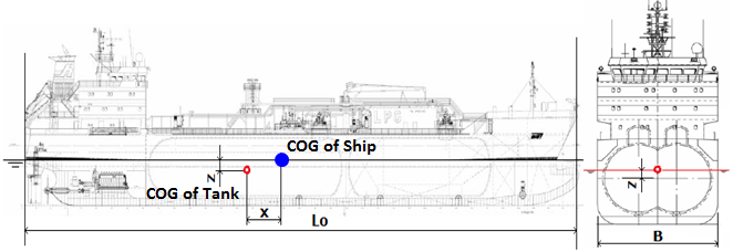 | |||
| Lo = length of the ship for determination of scantlings as defined in recognized standards (m); 선박의 최대 길이 | Lo = | 132.0 | m |
| B = greatest moulded breadth of the ship (m); 선박의 최대 폭 | B = | 23.0 | m |
| x = longitudinal distance (m) from amidships to the centre of gravity of the tank with contents; x is positive forward of amidships, negative aft of amidships; 선박의 중앙 에서 Tank 의 중심까지 거리, 선수방향을 정(+), 선미방향을 부(-) | x = | -50.0 | m |
| y = transverse distance (m) from centreline to the centre of gravity of the tank with contents; 선박의 횡방향 중앙에서 Tank 의 중심까지 떨어진 거리 | y = | 0.0 | m |
| z = vertical distance (m) from the ship's actual waterline to the centre of gravity of tank with contents; z is positive above and negative below the waterline; 선박의 흘수선에서 Tank 의 중심까지 높이, 홀수선상으로부터 상을 정(+), 하를 부(-) | z = | 7.0 | m |
| CB = block coefficient; [help] | CB = | 0.787 | |
| K = 1 in general. For particular loading conditions and hull forms, determination of K according to the following formula may be necessary; K = 13*GM/B, where K ≥ 1 and GM = metacentric height, GM = 1 (m); |
K = | 1.9 | |
 | A = | 0.652 | |
| V = service speed (knots); | V = | 12.0 | knots |
| Acceleration due to ship's motions : | |||
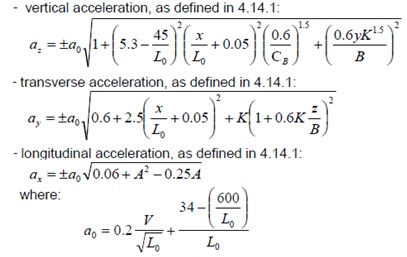 | az = | 0.7190 | g |
| ay = | 0.8977 | g | |
| ax = | 0.2452 | g | |
| a0 = | 0.4320 | g | |
| 1. Design Data | ||||
| Description | Symbol | Cylinder | BI-LOBE | Unit |
| Tank Dia. | D = | 7100 | mm | |
| Design Liquiod level | DLL = | 7100 | mm | |
| Radius of tank | R = | 3550 | mm | |
| Tank center to Swash Bulk Head (For Bilobe) | C = | 0 | 0 | mm |
| Dimension x, (Tank T.L to T.L) | x = | 23000 | mm | |
| Dimension y | y = | 0 | mm | |
| Dimension z, z = DLL - R | z = | 3550 | mm | |
| Tank Total Length | L=2R+x | 30100 | mm | |
| 2. Internal liquid pressure calculation [ as per IGC CODE] | ||||
| Design Internal pressure ( Design Data ) | Po = | 4.5 | bar.g | |
| MARVS ( Design Data ) | MARVS = | 4.5 | bar.g | |
| Internal liquid pressure ( Calculated IGC CODE ) Pgd(max) = Max(Pgd_x, Pgd_y) | Pgd(max) = | 0.7248 | bar.g | |
| Total Design Pressure : Peq = Po + (Pgd)max | Peq = | 5.2248 | bar.g | |
| Description | Symbol | Y-Z plane | X-Z plane | Unit |
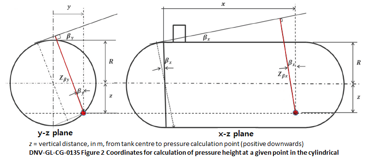
| Pgd : Internal liquid pressure ( IGC 4.28.1.2 ) Pgd = aβ · Zβ · ( ρ / 10-4 ) [bar.g] | Pgd = | 0.5983 | 0.7248 | bar.g |
| ρ : Design Density of LNG | ρ = | 500 | 500 | kg/m³ |
| aβ : dimensionless acceleration, resulting from gravitational and dynamic loads in an arbitrary direction β | aβ = | 1.7190 | 1.4931 | g |
| Zβ : largest liquid height (m) above the point where the pressure is to be determined measured from the Tank shell in the β direction | Zβ = | 7.100 | 9.903 | m |
| β : angles of resulting acceleration vector in relative to the vertical plane | β = | 0 | 7 | deg. |
| βmax : maximum angle (Full Loading Condition) | βmax = | 52.253 | 19.433 | deg. |
| β = βmax(FWD) : Maximum angle (Collision Crash Stop), ax = 0.5g β = βmax(AFD) : Maximum angle (Collision Crash Stop), ax = -0.25g | βmax = | 26.565 14.036 | deg. deg. | |
 | ||||
| 3.1 Dynamic Pressure Calculation Result (Max. Accelation and Max. Pgd(Max) | |||||||||||||||
| Sloshing Load Calculation (Full loading) |
Collision Crash Stop(FWD) ax = 0.5g |
Collision Crash Stop(AFD) ax =-0.25g | |||||||||||||
| Transverse (y-z plane) | Longitudinal (x-z plane) |
Longitudinal (x-z plane) | Longitudinal (x-z plane) | ||||||||||||
| β (deg) | aβ (g) | Zβ (m) | Pgd (bar.g) | β (deg) | aβ (g) | Zβ (m) | Pgd (bar.g) | β (deg) | aβ (g) | Zβ (m) | Pgd (bar.g) | β (deg) | aβ (g) | Zβ (m) | Pgd (bar.g) |
| 0 | 1.7190 | 7.1000 | 0.5983 | 7 | 1.4931 | 9.9030 | 0.7248 | 26.565 | 1.1180 | 17.3859 | 0.9528 | 14.036 | 1.0308 | 12.6782 | 0.6406 |
| 3.2 Dynamic Pressure Calculation by Each Angle | |||||||||||||||
| Sloshing Load Calculation (Full loading) |
Collision Crash Stop(FWD) ax = 0.5g |
Collision Crash Stop(AFD) ax =-0.25g | |||||||||||||
| (측면) Transverse (y-z plane) | (길이) Longitudinal (x-z plane) | (길이) Longitudinal (x-z plane) | (길이) Longitudinal (x-z plane) | ||||||||||||
| β (deg) | aβ (g) | Zβ (m) | Pgd (bar.g) | β (deg) | aβ (g) | Zβ (m) | Pgd (bar.g) | β (deg) | aβ (g) | Zβ (m) | Pgd (bar.g) | β (deg) | aβ (g) | Zβ (m) | Pgd (bar.g) |
| 0 | 1.7190 | 7.100 | 0.5983 | 0 | 1.7190 | 7.100 | 0.5983 | 0 | 1.0000 | 7.100 | 0.3480 | 0 | 1.0000 | 7.100 | 0.3480 |
| 1 | 1.7189 | 7.100 | 0.5982 | 1 | 1.7139 | 7.501 | 0.6302 | 1 | 1.0002 | 7.501 | 0.3678 | 1 | 1.0002 | 7.501 | 0.3678 |
| 2 | 1.7184 | 7.100 | 0.5981 | 2 | 1.6987 | 7.903 | 0.6581 | 2 | 1.0006 | 7.903 | 0.3876 | 2 | 1.0006 | 7.903 | 0.3876 |
| 3 | 1.7177 | 7.100 | 0.5978 | 3 | 1.6738 | 8.304 | 0.6813 | 3 | 1.0014 | 8.304 | 0.4076 | 3 | 1.0014 | 8.304 | 0.4076 |
| 4 | 1.7168 | 7.100 | 0.5975 | 4 | 1.6399 | 8.704 | 0.6997 | 4 | 1.0024 | 8.704 | 0.4277 | 4 | 1.0024 | 8.704 | 0.4277 |
| 5 | 1.7155 | 7.100 | 0.5971 | 5 | 1.5979 | 9.105 | 0.7131 | 5 | 1.0038 | 9.105 | 0.4480 | 5 | 1.0038 | 9.105 | 0.4480 |
| 6 | 1.7139 | 7.100 | 0.5965 | 6 | 1.5486 | 9.504 | 0.7215 | 6 | 1.0055 | 9.504 | 0.4685 | 6 | 1.0055 | 9.504 | 0.4685 |
| 7 | 1.7121 | 7.100 | 0.5959 | 7 | 1.4931 | 9.903 | 0.7248 | 7 | 1.0075 | 9.903 | 0.4891 | 7 | 1.0075 | 9.903 | 0.4891 |
| 8 | 1.7099 | 7.100 | 0.5951 | 8 | 1.4325 | 10.301 | 0.7233 | 8 | 1.0098 | 10.301 | 0.5099 | 8 | 1.0098 | 10.301 | 0.5099 |
| 9 | 1.7075 | 7.100 | 0.5943 | 9 | 1.3679 | 10.698 | 0.7173 | 9 | 1.0125 | 10.698 | 0.5310 | 9 | 1.0125 | 10.698 | 0.5310 |
| 10 | 1.7047 | 7.100 | 0.5933 | 10 | 1.3002 | 11.094 | 0.7071 | 10 | 1.0154 | 11.094 | 0.5522 | 10 | 1.0154 | 11.094 | 0.5522 |
| 11 | 1.7016 | 7.100 | 0.5922 | 11 | 1.2303 | 11.489 | 0.6929 | 11 | 1.0187 | 11.489 | 0.5737 | 11 | 1.0187 | 11.489 | 0.5737 |
| 12 | 1.6982 | 7.100 | 0.5910 | 12 | 1.1588 | 11.882 | 0.6749 | 12 | 1.0223 | 11.882 | 0.5954 | 12 | 1.0223 | 11.882 | 0.5954 |
| 13 | 1.6944 | 7.100 | 0.5897 | 13 | 1.0864 | 12.274 | 0.6536 | 13 | 1.0263 | 12.274 | 0.6175 | 13 | 1.0263 | 12.274 | 0.6175 |
| 14 | 1.6901 | 7.100 | 0.5882 | 14 | 1.0106 | 12.678 | 0.6281 | 14 | 1.0308 | 12.678 | 0.6406 | 14.036 | 1.0308 | 12.678 | 0.6406 |
| 15 | 1.6858 | 7.100 | 0.5867 | 15 | 0.9395 | 13.053 | 0.6011 | 15 | 1.0353 | 13.053 | 0.6624 | ||||
| 16 | 1.6809 | 7.100 | 0.5850 | 16 | 0.8647 | 13.440 | 0.5697 | 16 | 1.0403 | 13.440 | 0.6854 | ||||
| 17 | 1.6757 | 7.100 | 0.5832 | 17 | 0.7878 | 13.824 | 0.5339 | 17 | 1.0457 | 13.824 | 0.7086 | ||||
| 18 | 1.6700 | 7.100 | 0.5812 | 18 | 0.7056 | 14.207 | 0.4914 | 18 | 1.0515 | 14.207 | 0.7323 | ||||
| 19 | 1.6640 | 7.100 | 0.5791 | 19.433 | 0.6058 | 14.588 | 0.4332 | 19 | 1.0576 | 14.588 | 0.7563 | ||||
| 20 | 1.6575 | 7.100 | 0.5769 | 20 | 1.0642 | 14.966 | 0.7808 | ||||||||
| 21 | 1.6505 | 7.100 | 0.5744 | 21 | 1.0711 | 15.342 | 0.8056 | ||||||||
| 22 | 1.6430 | 7.100 | 0.5718 | 22 | 1.0785 | 15.716 | 0.8309 | ||||||||
| 23 | 1.6351 | 7.100 | 0.5691 | 23 | 1.0864 | 16.087 | 0.8567 | ||||||||
| 24 | 1.6266 | 7.100 | 0.5661 | 24 | 1.0946 | 16.455 | 0.8829 | ||||||||
| 25 | 1.6176 | 7.100 | 0.5630 | 25 | 1.1034 | 16.820 | 0.9098 | ||||||||
| 26 | 1.6023 | 7.100 | 0.5577 | 26.565 | 1.1180 | 17.386 | 0.9528 | ||||||||
| 27 | 1.5977 | 7.100 | 0.5561 | ||||||||||||
| 28 | 1.5869 | 7.100 | 0.5523 | ||||||||||||
| 29 | 1.5754 | 7.100 | 0.5483 | ||||||||||||
| 30 | 1.5631 | 7.100 | 0.5440 | ||||||||||||
| 31 | 1.5501 | 7.100 | 0.5395 | ||||||||||||
| 32 | 1.5364 | 7.100 | 0.5347 | ||||||||||||
| 33 | 1.5217 | 7.100 | 0.5296 | ||||||||||||
| 34 | 1.5062 | 7.100 | 0.5242 | ||||||||||||
| 35 | 1.4898 | 7.100 | 0.5185 | ||||||||||||
| 36 | 1.4723 | 7.100 | 0.5124 | ||||||||||||
| 37 | 1.4538 | 7.100 | 0.5060 | ||||||||||||
| 38 | 1.4341 | 7.100 | 0.4991 | ||||||||||||
| 39 | 1.4131 | 7.100 | 0.4918 | ||||||||||||
| 40 | 1.3908 | 7.100 | 0.4841 | ||||||||||||
| 41 | 1.3670 | 7.100 | 0.4758 | ||||||||||||
| 42 | 1.3416 | 7.100 | 0.4669 | ||||||||||||
| 43 | 1.3144 | 7.100 | 0.4575 | ||||||||||||
| 44 | 1.2851 | 7.100 | 0.4473 | ||||||||||||
| 45 | 1.2536 | 7.100 | 0.4363 | ||||||||||||
| 46 | 1.2194 | 7.100 | 0.4244 | ||||||||||||
| 47 | 1.1820 | 7.100 | 0.4114 | ||||||||||||
| 48 | 1.1406 | 7.100 | 0.3970 | ||||||||||||
| 49 | 1.0939 | 7.100 | 0.3807 | ||||||||||||
| 50 | 1.0397 | 7.100 | 0.3619 | ||||||||||||
| 51 | 0.9725 | 7.100 | 0.3385 | ||||||||||||
| 52.253 | 0.8684 | 7.100 | 0.3022 | ||||||||||||
3. Tank 용량별 Dia. 비교표
| 구분 | Hemi-Spherical Vessel | 2:1 Ellipsoidal Head Vessel | 10% Dish-Head Vessel | |||||||||||||||
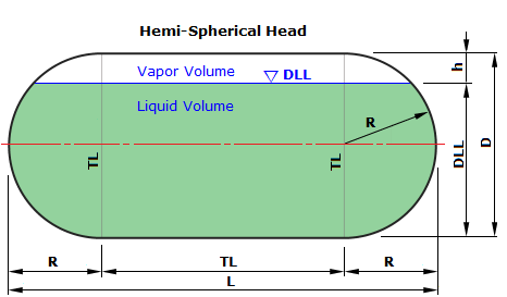 | 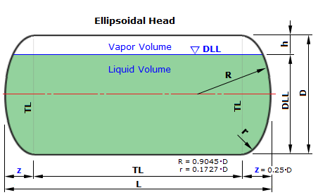 | 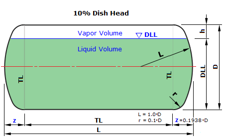 | ||||||||||||||||
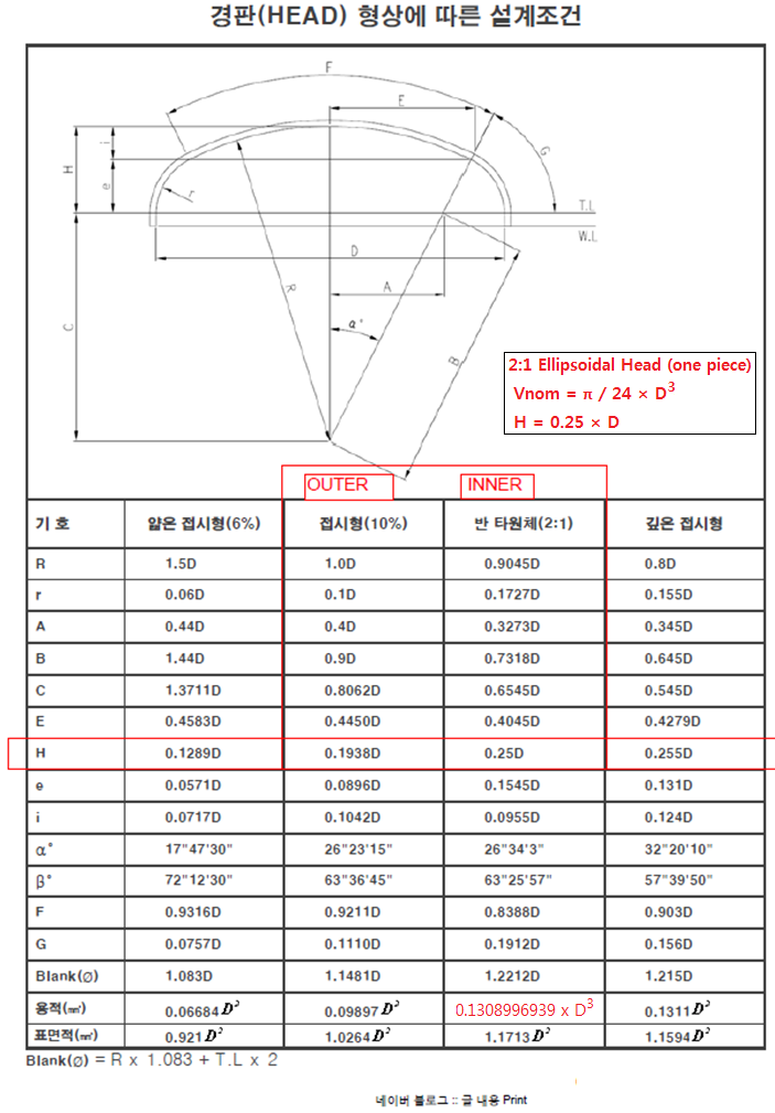
| R = 0.5×D, Vnom = π×[(D³/ 6) + (D²× L / 4)] | R = 0.9045×D, r = 0.172744×D, z = 0.25×D, Vnom = (π×D³/12) + (L×π×D²/4) | L = 1.0×D, r = 0.1×D, z=0.193774×D, C=0.3780223, Vnom = (2×C×π×D³/12) + (L×π×D²/4) | ||||||||||||||||
| 번호 | Dia (m) | TL TO TL Length (m) | Head End to End Length (m) | 1) HEAD Volume(m) | 2) Cylinder Volume(m) |
3) 공칭용량 Total Volume(m) | Dia (m) | TL TO TL Length (m) | Head End to End Length (m) | 1) HEAD Volume(m) | 2) Cylinder Volume(m) |
3) 공칭용량 Total Volume(m) | Dia (m) | TL TO TL Length (m) | Head End to End Length (m) | 1) HEAD Volume(m) | 2) Cylinder Volume(m) |
3) 공칭용량 Total Volume(m) |
| 1 | 12.500 | 40.267 | 52.767 | 1022.654 | 4941.463 | 5964.117 | 12.500 | 44.433 | 50.683 | 511.327 | 5452.790 | 5964.117 | 12.500 | 45.450 | 50.175 | 386.586 | 5577.531 | 5964.117 |
| 2 | 12.600 | 39.432 | 52.032 | 1047.394 | 4916.723 | 5964.117 | 12.600 | 43.632 | 49.932 | 523.697 | 5440.420 | 5964.117 | 12.600 | 44.656 | 49.419 | 395.938 | 5568.179 | 5964.117 |
| 3 | 12.700 | 38.615 | 51.315 | 1072.531 | 4891.586 | 5964.117 | 12.700 | 42.848 | 49.198 | 536.265 | 5427.852 | 5964.117 | 12.700 | 43.881 | 48.682 | 405.441 | 5558.676 | 5964.117 |
| 4 | 12.800 | 37.815 | 50.615 | 1098.066 | 4866.051 | 5964.117 | 12.800 | 42.082 | 48.482 | 549.033 | 5415.084 | 5964.117 | 12.800 | 43.123 | 47.961 | 415.094 | 5549.023 | 5964.117 |
| 5 | 12.900 | 37.033 | 49.933 | 1124.004 | 4840.113 | 5964.117 | 12.900 | 41.333 | 47.783 | 562.002 | 5402.115 | 5964.117 | 12.900 | 42.382 | 47.258 | 424.898 | 5539.219 | 5964.117 |
| 6 | 13.000 | 36.267 | 49.267 | 1150.347 | 4813.770 | 5964.117 | 13.000 | 40.600 | 47.100 | 575.173 | 5388.944 | 5964.117 | 13.000 | 41.657 | 46.572 | 434.857 | 5529.260 | 5964.117 |
| 7 | 13.100 | 35.517 | 48.617 | 1177.098 | 4787.019 | 5964.117 | 13.100 | 39.883 | 46.433 | 588.549 | 5375.568 | 5964.117 | 13.100 | 40.949 | 45.901 | 444.969 | 5519.148 | 5964.117 |
| 8 | 13.200 | 34.782 | 47.982 | 1204.260 | 4759.857 | 5964.117 | 13.200 | 39.182 | 45.782 | 602.130 | 5361.987 | 5964.117 | 13.200 | 40.256 | 45.245 | 455.237 | 5508.880 | 5964.117 |
| 9 | 13.300 | 34.063 | 47.363 | 1231.838 | 4732.279 | 5964.117 | 13.300 | 38.496 | 45.146 | 615.919 | 5348.198 | 5964.117 | 13.300 | 39.577 | 44.605 | 465.662 | 5498.455 | 5964.117 |
| 10 | 13.400 | 33.358 | 46.758 | 1259.833 | 4704.284 | 5964.117 | 13.400 | 37.824 | 44.524 | 629.917 | 5334.200 | 5964.117 | 13.400 | 38.914 | 43.979 | 476.245 | 5487.872 | 5964.117 |
| 11 | 13.500 | 32.667 | 46.167 | 1288.249 | 4675.868 | 5964.117 | 13.500 | 37.167 | 43.917 | 644.125 | 5319.992 | 5964.117 | 13.500 | 38.264 | 43.368 | 486.987 | 5477.130 | 5964.117 |
| 12 | 13.600 | 31.990 | 45.590 | 1317.090 | 4647.027 | 5964.117 | 13.600 | 36.523 | 43.323 | 658.545 | 5305.572 | 5964.117 | 13.600 | 37.629 | 42.770 | 497.889 | 5466.228 | 5964.117 |
| 13 | 13.700 | 31.326 | 45.026 | 1346.357 | 4617.760 | 5964.117 | 13.700 | 35.892 | 42.742 | 673.179 | 5290.938 | 5964.117 | 13.700 | 37.006 | 42.185 | 508.953 | 5455.164 | 5964.117 |
| 14 | 13.800 | 30.675 | 44.475 | 1376.055 | 4588.062 | 5964.117 | 13.800 | 35.275 | 42.175 | 688.028 | 5276.089 | 5964.117 | 13.800 | 36.397 | 41.614 | 520.180 | 5443.937 | 5964.117 |
| 15 | 13.900 | 30.036 | 43.936 | 1406.187 | 4557.930 | 5964.117 | 13.900 | 34.670 | 41.620 | 703.093 | 5261.024 | 5964.117 | 13.900 | 35.800 | 41.055 | 531.570 | 5432.547 | 5964.117 |
| 16 | 14.000 | 29.410 | 43.410 | 1436.755 | 4527.362 | 5964.117 | 14.000 | 34.077 | 41.077 | 718.378 | 5245.739 | 5964.117 | 14.000 | 35.215 | 40.508 | 543.125 | 5420.992 | 5964.117 |
| 17 | 14.100 | 28.796 | 42.896 | 1467.763 | 4496.354 | 5964.117 | 14.100 | 33.496 | 40.546 | 733.882 | 5230.235 | 5964.117 | 14.100 | 34.643 | 39.973 | 554.847 | 5409.270 | 5964.117 |
| 18 | 14.200 | 28.193 | 42.393 | 1499.214 | 4464.903 | 5964.117 | 14.200 | 32.927 | 40.027 | 749.607 | 5214.510 | 5964.117 | 14.200 | 34.081 | 39.449 | 566.736 | 5397.381 | 5964.117 |
| 19 | 14.300 | 27.602 | 41.902 | 1531.111 | 4433.006 | 5964.117 | 14.300 | 32.368 | 39.518 | 765.556 | 5198.561 | 5964.117 | 14.300 | 33.531 | 38.937 | 578.794 | 5385.323 | 5964.117 |
| 20 | 14.400 | 27.021 | 41.421 | 1563.458 | 4400.659 | 5964.117 | 14.400 | 31.821 | 39.021 | 781.729 | 5182.388 | 5964.117 | 14.400 | 32.992 | 38.436 | 591.022 | 5373.095 | 5964.117 |
| 21 | 14.500 | 26.451 | 40.951 | 1596.256 | 4367.861 | 5964.117 | 14.500 | 31.284 | 38.534 | 798.128 | 5165.989 | 5964.117 | 14.500 | 32.463 | 37.945 | 603.420 | 5360.697 | 5964.117 |
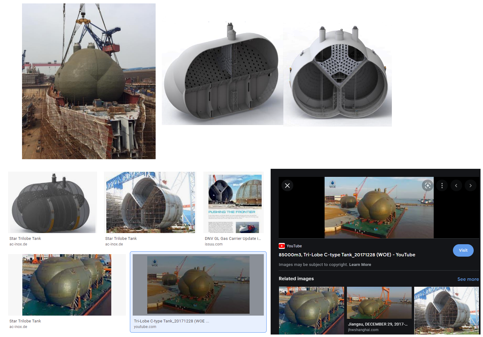
유튜브 보기
	var Di  = 2210;
	var Ri  = Di / 2;
	var DLL = 1853;

	var z = 552.5 ;
	var C = 2 * 552.5 / 2210;
	C	= 0.5;

    var V_one_head = Math.pow(Di,3) * C * ( Math.PI / 12) * ( 3 * Math.pow((DLL / Di ),2) - 2 * Math.pow((DLL/Di),3));
	var V_Cylinder = L * ( Ri^2 * Math.acos((Ri-DLL)/Ri) - (Ri - DLL) * Math.sqrt(Di * DLL - Math.pow(DLL,2)));

	var V = V_one_head + V_Cylinder;
	https://stackoverflow.com/questions/2172798/how-to-draw-an-oval-in-html5-canvas
	There doesnt seem to be a native function to draw an oval-like shape. Also i am not looking for the egg-shape.
	Is it possible to draw an oval with 2 bezier curves? Somebody expierenced with that?
	My purpose is to draw some eyes and actually im just using arcs. Thanks in advance. Solution
	So scale() changes the scaling for all next shapes. Save() saves the settings before and restore is used to restore the settings to draw new shapes without scaling.
	Thanks to Jani

	ctx.save();
	ctx.scale(0.75, 1);
	ctx.beginPath();
	ctx.arc(20, 21, 10, 0, Math.PI*2, false);
	ctx.stroke();
	ctx.closePath();
	ctx.restore();
시작시간 = [2025-12-26 11:47:59.0324]
종료시간 = [2025-12-26 11:47:59.0333]
PRT_IMO_FORMULA_BUNSU() / FUNCTION_MATH.jsp 에 있음 출처 : ASME SHELL THICKNESS CALCULATION 출처
|
Wall thickness calculation of Sphere
according ASME |
||||||||||||||
| Allowable stress | S = | 175.2 = | 175.20 N/mm² | |||||||||||
| Corroded thickness | tc = t - Ca - tol = | 8.2 - 1 - 1.03 = | 6.17 mm | |||||||||||
| Sphere: | ||||||||||||||
| Corroded inside radius |
|
|
103.38 mm | |||||||||||
| 1. | Cylinder Shell : +-×÷ Required wall thickness |
|
| 0.15 mm | ||||||||||
| 2. | Spherical Head : Required wall thickness |
|
| 0.15 mm | ||||||||||
| 3. | 2:1 Ellipsoidal Head : Required wall thickness |
|
| 0.15 mm | ||||||||||
| 3. | 10% Dish Head : Required wall thickness |
|
| 0.15 mm | ||||||||||
| Nominal required thickness | trn = tr + Ca + tol = | 0.148 + 1 + 1.03 = | 2.18 mm | |||||||||||
| Max. Allowable Working Press. |
|
|
20.67 N/mm² | |||||||||||
| Thickness analysis, t > trn ? | t = 8.2 mm is OK | |||||||||||||
| Weight | 9.00 kg | |||||||||||||
| Enclosed volume | 0.004 m3 | |||||||||||||
출처 : 이미지를 캔버스에 넣은후 캔버스 이미지를 로칼스트리지에 저장하는 방법 (바로가기 누르세요)
[바로가기]
테스트 하기 (누르세요)

HTML에서 LATEX Math Library 수식 표현하기 https://www.scientificpsychic.com/etc/square-root.html
네이버 블로그 / HTML에서 수식 표현하기 https://blog.daum.net/asfreeas/18314217
| _______ | |
| √ | X2 + 1 |
| −b ± √ b2 − 4ac |
| 2a |
HTML 특수문자 리스트
| Α α | αλφα | Alpha (알파) 한국어 '아' (영어 cup 의 u 또는 calm 의 a) |
| Β β | βητα | Beta (베타) 영어 b |
| Γ γ | γαμμα | Gamma (감마) 영어 get 의 g |
| Δ δ | δελτα | Delta (델타) 영어 d |
| Ε ε | εψιλον | Epsilon (엡실론) 한국어 짧은 '에' (영어 bed 의 e) |
| Ζ ζ | ζετα | Zeta (제타) 영어 zd (나중에 z 로 바뀜) |
| Η η | ητα | Eta (에타) 한국어 긴 '에' (영어 play 의 ay) |
| Θ θ | θητα | Theta (세타) 한국어 'ㅌ' (나중에 영어 thank 의 th 로 바뀜) |
| Ι ι | ιωτα | Iota (이오타) 한국어 '이' (영어 fit 의 i 또는 feet 의 ee) |
| Κ κ | καππα | Kappa (카파) 한국어 'ㄲ' (영어 k) |
| Λ λ | λαμβδα | Lambda (람다) 영어 l |
| Μ μ | μυ | Mu (뮤) 영어 m |
| Ν ν | νυ | Nu (뉴) 영어 n |
| Ξ ξ | Ξ ξ | Xi (크사이) 영어 box 의 x |
| Ο ο | ομικρον | Omicron (오미크론) 한국어 '오' (영국영어 pot 의 o) |
| Π π | πι | Pi (파이) 한국어 'ㅃ' (영어 p) |
| Ρ ρ | ρω | Rho (로우) 한국어 '사랑' 의 'ㄹ' (영어 r) |
| Σ σ | σιγμα | Sigma (시그마) 영어 sing 의 s 시그마의 소문자는 위와 같이 두 가지입니다. 첫 번째는 단어 중간에 올 때 쓰이고 두 번째는 단어 끝에 올 때 쓰입니다. |
| Τ τ | ταυ | Tau (타우) 영어 t (한국어 된소리 'ㄸ') |
| Υ υ | υψιλον | Upsilon (웁실론) 프랑스어 u (한국어 '위' 와 비슷) 또는 영어 u |
| Φ φ | φι | Phi (파이) 한국어 'ㅍ' (나중에 영어 f 로 바뀜) |
| Χ χ | χι | 카이 (xhi) 한국어 'ㅋ' (나중에 독일어 Buch 의 ch 로 바뀜) |
| Ψ ψ | ψι | 프사이 (psi) 영어 ps |
| Ω ω | ωμεγα | Omega (오메가) 한국어 '오' (영어 tone 의 o) |
| α ι | αυ | 영어 high 의 이중모음과 같습니다. 영어 how 의 이중모음과 같습니다. |
| ε ι | ευ, ηυ | 한국어 '에' 보다 조금 긴 소리입니다. 한국어 '에' 와 '우' 를 각각 발음합니다. |
| ο ι | ο ι | 영어 boy 의 이중모음과 같습니다. |
| ο υ | ο υ | 영어 too 의 장모음과 같습니다. |
| υ ι | υ ι | 영어 quit 의 ui 소리와 같습니다. |
| γ γ | γ γ | 영어 finger 의 ng 발음입니다. |
| 다른 자음들이 이중으로 나타나면 각각을 발음합니다. | ||
HTML 특수문자 리스트
출처 : http://kor.pe.kr/util/4/charmap2.htm| HTML 상에서 특수문자가 제대로 나타나지 않을 수 있기 때문에 아래 문자들를 사용합니다. | |||
| 표현문자 | 숫자표현 | 문자표현 | 설명 |
| - | �- | - | 사용하지 않음 |
| space | 	 | - | 수평탭 |
| space | | - | 줄 삽입 |
| - | - | - | 사용하지 않음 |
| space |   | - | 여백 |
| ! | ! | - | 느낌표 |
| \" | " | " | 따옴표 |
| # | # | - | 숫자기호 |
| $ | $ | - | 달러 |
| % | % | - | 백분율 기호 |
| & | & | & | Ampersand |
| ' | ' | - | 작은 따옴표 |
| ( | ( | - | 왼쪽 괄호 |
| ) | ) | - | 오른쪽 괄호 |
| * | * | - | 아스트릭 |
| + | + | - | 더하기 기호 |
| , | , | - | 쉼표 |
| - | - | - | Hyphen |
| . | . | - | 마침표 |
| / | / | - | Solidus (slash) |
| 0 - 9 | 0-9 | - | 0부터 9까지 |
| : | : | - | 콜론 |
| ; | ; | - | 세미콜론 |
| < | < | < | 보다 작은 |
| = | = | - | 등호 |
| > | > | > | 보다 큰 |
| ? | ? | - | 물음표 |
| @ | @ | - | Commercial at |
| A - Z | A-Z | - | A부터 Z까지 |
| [ | [ | - | 왼쪽 대괄호 |
| \ | \ | - | 역슬래쉬 |
| ] | ] | - | 오른쪽 대괄호 |
| ^ | ^ | - | 탈자부호 |
| _ | _ | - | 수평선 |
| ` | ` | - | Acute accent |
| a - z | a-z | - | a부터 z까지 |
| { | { | - | 왼쪽 중괄호 |
| | | | | - | 수직선 |
| } | } | - | 오른쪽 중괄호 |
| ~ | ~ | - | 꼬리표 |
| - | -Ÿ | - | 사용하지 않음 |
|   | | Non-breaking space | |
| ¡ | ¡ | ¡ | 거꾸로된 느낌표 |
| ¢ | ¢ | ¢ | 센트 기호 |
| £ | £ | £ | 파운드 |
| ¤ | ¤ | ¤ | 현재 환율 |
| ¥ | ¥ | ¥ | 엔 |
| | | ¦ | ¦ | 끊어진 수직선 |
| § | § | § | 섹션 기호 |
| ¨ | ¨ | ¨ | 움라우트 |
| ⓒ | © | © | 저작권 |
| ª | ª | ª | Feminine ordinal |
| ≪ | « | « | 왼쪽 꺾인 괄호 |
| ¬ | ¬ | ¬ | 부정 |
| | ­ | ­ | Soft hyphen |
| ? | ® | ® | 등록상표 |
| &hibar; | ¯ | ¯ | Macron accent |
| ° | ° | ° | Degree sign |
| ± | ± | ± | Plus or minus |
| ² | ² | ² | Superscript two |
| ³ | ³ | ³ | Superscript three |
| ´ | ´ | ´ | Acute accent |
| μ | µ | µ | Micro sign (Mu) |
| ¶ | ¶ | ¶ | 문단기호 |
| · | · | · | Middle dot |
| ¸ | ¸ | ¸ | Cedilla |
| ¹ | ¹ | ¹ | Superscript one |
| º | º | º | Masculine ordinal |
| ≫ | » | » | 오른쪽 꺾인 괄호 |
| ¼ | ¼ | ¼ | 4분의 1 |
| ½ | ½ | ½ | 2분의 1 |
| ¾ | ¾ | ¾ | 4분의 3 |
| ¿ | ¿ | ¿ | 거꾸로된 물음표 |
| À | À | Capital A, grave accent | |
| Á | Á | Capital A, acute accent | |
| Â | Â | Capital A, circumflex accent | |
| Ã | Ã | Capital A, tilde | |
| Ä | Ä | Capital A, dieresis or umlaut mark | |
| Å | Å | Capital A, ring (Angstrom) | |
| Æ | Æ | Æ | Capital AE diphthong (ligature) |
| C | Ç | Ç | Capital C, cedilla |
| E | È | È | Capital E, grave accent |
| E | É | É | Capital E, acute accent |
| E | Ê | Ê | Capital E, circumflex accent |
| E | Ë | Ë | Capital E, dieresis or umlaut mark |
| I | Ì | Ì | Capital I, grave accent |
| I | Í | Í | Capital I, acute accent |
| I | Î | Î | Capital I, circumflex accent |
| I | Ï | Ï | Capital I, dieresis or umlaut mark |
| Ð | Ð | Ð | Capital Eth, Icelandic |
| N | Ñ | Ñ | Capital N, tilde |
| O | Ò | Ò | Capital O, grave accent |
| O | Ó | Ó | Capital O, acute accent |
| O | Ô | Ô | Capital O, circumflex accent |
| O | Õ | Õ | Capital O, tilde |
| O | Ö | Ö | Capital O, dieresis or umlaut mark |
| × | × | × | Multiply sign |
| Ø | Ø | Ø | width=130 Capital O, slash |
| U | Ù | Ù | Capital U, grave accent |
| U | Ú | Ú | Capital U, acute accent |
| U | Û | Û | Capital U, circumflex accent |
| U | Ü | Ü | Capital U, dieresis or umlaut mark |
| Y | Ý | Ý | Capital Y, acute accent |
| Þ | Þ | Þ | Capital Thorn, Icelandic |
| ß | ß | ß | Small sharp s, German (sz ligature) |
| à | à | Small a, grave accent | |
| á | á | Small a, acute accent | |
| â | â | Small a, circumflex accent | |
| ã | ã | Small a, tilde | |
| ä | ä | Small a, dieresis or umlaut mark | |
| å | å | Small a, ring | |
| æ | æ | æ | Small ae diphthong (ligature) |
| c | ç | ç | Small c, cedilla |
| e | è | è | Small e, grave accent |
| e | é | é | Small e, acute accent |
| e | ê | ê | Small e, circumflex accent |
| e | ë | ë | Small e, dieresis or umlaut mark |
| i | ì | ì | Small i, grave accent |
| i | í | í | Small i, acute accent |
| i | î | î | Small i, circumflex accent |
| i | ï | ï | Small i, dieresis or umlaut mark |
| ð | ð | ð | Small eth, Icelandic |
| n | ñ | ñ | Small n, tilde |
| o | ò | ò | Small o, grave accent |
| o | ó | ó | Small o, acute accent |
| o | ô | ô | Small o, circumflex accent |
| o | õ | õ | Small o, tilde |
| o | ö | ö | Small o, dieresis or umlaut mark |
| ÷ | ÷ | ÷ | Division sign |
| ø | ø | ø | Small o, slash |
| u | ù | ù | Small u, grave accent |
| u | ú | ú | Small u, acute accent |
| u | û | û | Small u, circumflex accent |
| u | ü | ü | Small u, dieresis or umlaut mark |
| y | ý | ý | Small y, acute accent |
| þ | þ | þ | Small thorn, Icelandic |
| y | ÿ | ÿ | Small y, dieresis or umlaut mark |
HTML END!!!
